
Ash conveying system of coal-fired power plant

A technology for power plants and ash transportation, which is applied to conveyors, transportation and packaging, and transportation of bulk materials. It can solve problems that affect the normal production, affect the normal operation of equipment, increase maintenance costs, etc., and achieve economic value and energy-saving society. The benefits are considerable, the maintenance cost is saved, and the effect of saving electricity bills

Pending Publication Date: 2018-10-12
浙江鄞发节能科技有限公司
View PDF7 Cites 2 Cited by
  • Summary
  • Abstract
  • Description
  • Claims
  • Application Information

AI Technical Summary

Problems solved by technology

In addition, due to the high-pressure and high-temperature operating environment, the failure rate of the above-mentioned warehouse pump type pneumatic ash conveying system in the prior art is relatively high, which not only increases the maintenance cost, but also affects the normal operation of the equipment during the maintenance period, thereby affecting the normal production.
But so far, there is no effective and feasible technical solution to solve the above technical problems

Method used


Image

  • Ash conveying system of coal-fired power plant
  • Ash conveying system of coal-fired power plant
  • Ash conveying system of coal-fired power plant

Examples


Embodiment Construction

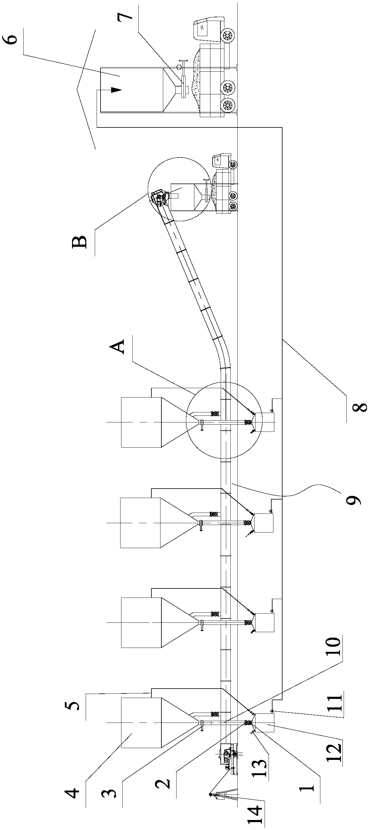
[0019]The specific embodiments of the present invention will be further described below in conjunction with the accompanying drawings. What needs to be declared here is that the descriptions of these specific implementations are used to help understand the present invention, but are not intended to limit the present invention. In addition, the technical features and technical means involved in the various specific embodiments of the present invention described below can be combined with each other as long as they do not constitute a conflict with each other.

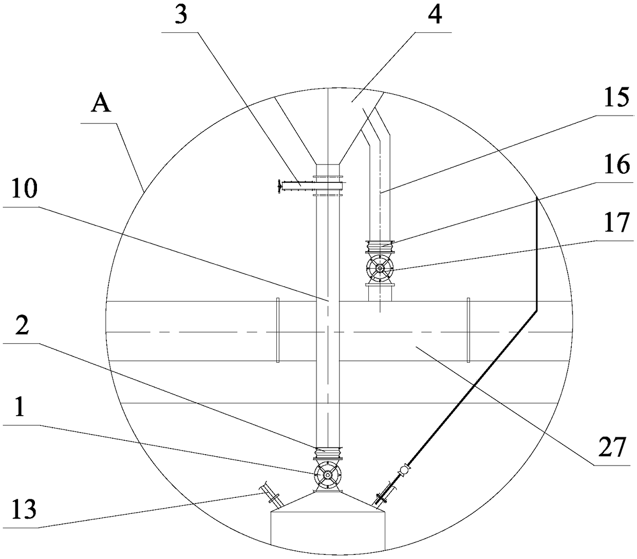
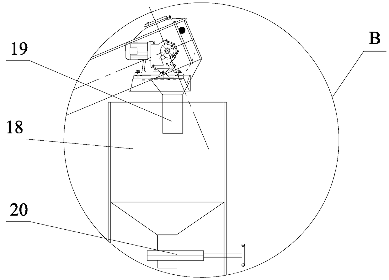
[0020] like figure 1 , figure 2 , image 3 As shown, the coal-fired power plant ash conveying system of the present invention includes a plurality of ash hoppers 4 for collecting the fly ash of the electric precipitator, each ash hopper 4 has a warehouse pump feed valve 1 below it, and the first ash discharge connecting pipe 10 is connected to the warehouse Pump feed valve 1 and a storage pump ash storage tank 12, th...


PUM


Abstract

The invention discloses an ash conveying system of a coal-fired power plant. The system comprises a plurality of ash buckets, a bin pump feeding valve, a first ash discharging connecting pipe which isconnected to the bin pump feeding valve, and a bin pump ash storing tank, wherein a compressed air connector is arranged on the bin pump ash storing tank; a discharging valve is arranged on the bin pump ash storing tank; a pressure ash conveying pipe is connected to a plurality of discharging valves and a pneumatic conveying ash storage; a first discharging valve is arranged at the bottom part ofthe pneumatic conveying ash storage; an additional ash conveying bypass system is mounted on an original bin pump type pneumatic ash conveying system, namely, the additional ash conveying bypass system is connected to a tooth cable type ash conveyor; the plurality of ash buckets for collecting coal ash of an electric dust collecting device are connected to the tooth cable type ash conveyor; an output port is formed in one end, far away from the plurality of ash buckets, of the tooth cable type ash conveyor; an automatic constant-force tensioning device is arranged at one end, far away from the output port, of the tooth cable type powder conveyor; and an extending section out of a section where a sealing box body is connected to each ash bucket is upwards inclined. With the adoption of theash conveying system of the coal-fired power plant, the electricity consumption cost is greatly decreased, and moreover, the production can be normally carried out without being influenced in the repairing period.

Description

technical field [0001] The invention relates to the technical field of conveying equipment in a coal-fired power plant, in particular to an ash conveying system for a coal-fired power plant downstream of the ash removal system of a coal-fired boiler. Background technique [0002] The fly ash removed by the coal-fired boiler ash removal system of the prior art coal-fired power plant is stored in multiple ash hoppers, and the fly ash in the multiple ash hoppers is transported to the ash store far away from the site for trucking The equipment transported to the comprehensive utilization site far away from the power plant is the warehouse pump type pneumatic ash conveying system, but the names are different, such as the pneumatic ash removal system, the positive pressure dense phase pneumatic ash removal system, the electric dust removal ash conveying system, etc. The system is also called device. [0003] The general structure of the warehouse pump type pneumatic ash conveying...

Claims


Application Information

Patent Timeline
IPC IPC(8): B65G53/16B65G53/46B65G53/44
CPCB65G53/16B65G53/44B65G53/46
Inventor 汪浩斌
Owner 浙江鄞发节能科技有限公司
Learn More