
Array beam alignment device and method for judging the alignment of 2×2 emitting light sources

A technology of array beams and determination methods, which is applied in optics, optical components, instruments, etc., can solve the problems of array beam drift characteristics that cannot be aligned

Active Publication Date: 2021-04-06
XIAN UNIV OF TECH
View PDF5 Cites 0 Cited by
  • Summary
  • Abstract
  • Description
  • Claims
  • Application Information

AI Technical Summary

Problems solved by technology

[0005] Another object of the present invention is to provide a method for judging the alignment of a 2×2 emitting light source based on a four-quadrant detector, which can solve the problem of misalignment caused by the drift characteristics of the array beam after transmission

Method used


Image

  • Array beam alignment device and method for judging the alignment of 2×2 emitting light sources
  • Array beam alignment device and method for judging the alignment of 2×2 emitting light sources
  • Array beam alignment device and method for judging the alignment of 2×2 emitting light sources

Examples


Embodiment Construction

[0040] The present invention will be described in detail below in conjunction with the accompanying drawings and specific embodiments.

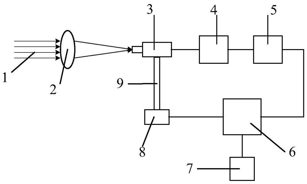
[0041] The invention provides an array beam alignment device, such as figure 2 As shown, it includes a 2×2 array beam 1, a lens 2, a four-quadrant detector 3 and a coupling 9. The 2×2 array beam 1 is focused on the photosensitive surface of the four-quadrant detector 3 after passing through the lens 2, and the four-quadrant detector The output end of the detector 3 is connected with an amplifier circuit 4, a filter device 5, a signal processing unit 6 and a two-dimensional motor 8 in sequence, the four-quadrant detector 3 is placed on the two-dimensional motor 8 through the support of the coupling 9, and the signal processing unit 6 A computer 7 is also connected, and the signal processing unit 6 is controlled by the computer 7 . The signal processing unit 6 used is the ARM processor of STM32F103ZET6.

[0042] The present invention also pr...


PUM


Abstract

The invention discloses an array beam alignment device, which includes a 2×2 array beam, a lens, a four-quadrant detector, an amplification circuit, a filter device, a signal processing unit, a computer, a two-dimensional motor and a shaft coupling, and the above-mentioned device The method for judging the alignment of the 2×2 emitting light source, specifically includes the following steps: focusing the 2×2 emitting light source on the photosensitive surface of the four-quadrant detector through the lens, and the four-quadrant detector converts the received optical signal into a four-way Electrical signal; the obtained four-way electrical signal is transmitted to the signal processing unit after a series of processing, and the amplified four-way electrical signal is compared and analyzed in the signal processing unit, and the energy of the four-way electrical signal is used to judge whether the light beam is right. According to the judgment result, the two-dimensional motor is controlled, and the two-dimensional motor drives the four-quadrant detector to adjust the position of the array beam and realize the alignment of the 2×2 emission light source. Addressed alignment issues with arrayed beams.

Description

technical field [0001] The invention belongs to the technical field of wireless laser communication, and in particular relates to a base array beam alignment device, and also relates to a judging method for aligning 2×2 emitting light sources by using the array beam alignment device. Background technique [0002] The wireless laser communication (Free-Space Optical communication, FSO) channel is dynamic and complex. When the laser is transmitted in the atmosphere, it is affected by atmospheric turbulence, resulting in atmospheric turbulence effects such as beam jitter, drift, and scintillation. Assuming that the detection device cannot detect the position change of the light spot in real time to drive the position adjustment of the receiving device, the communication link may be interrupted, thereby affecting the performance of the communication system. Therefore, a set of beam real-time automatic alignment system is needed to adjust the transmitting beam so that the transmi...

Claims


Application Information

Patent Timeline
Patent Type & Authority Patents(China)
IPC IPC(8): G02B27/00
CPCG02B27/00
Inventor 柯熙政王姣
Owner XIAN UNIV OF TECH
Learn More