
Light spot aligning method based on four-quadrant detector

A four-quadrant detector and light spot technology, applied in instruments, measuring devices, optical devices, etc., can solve the problem of difficult alignment of light spots, and achieve the effect of improving accuracy

Active Publication Date: 2017-05-31
XIAN UNIV OF TECH
View PDF3 Cites 17 Cited by
  • Summary
  • Abstract
  • Description
  • Claims
  • Application Information

AI Technical Summary

Problems solved by technology

[0004] The purpose of the present invention is to provide a light spot alignment method based on a four-quadrant detector, which solves the problem that the light spot is difficult to align when the light spot drift and the light beam are not parallel to the antenna visual axis.

Method used


Image

  • Light spot aligning method based on four-quadrant detector
  • Light spot aligning method based on four-quadrant detector
  • Light spot aligning method based on four-quadrant detector

Examples


Embodiment Construction

[0033] The present invention will be described in detail below in conjunction with the accompanying drawings and specific embodiments.

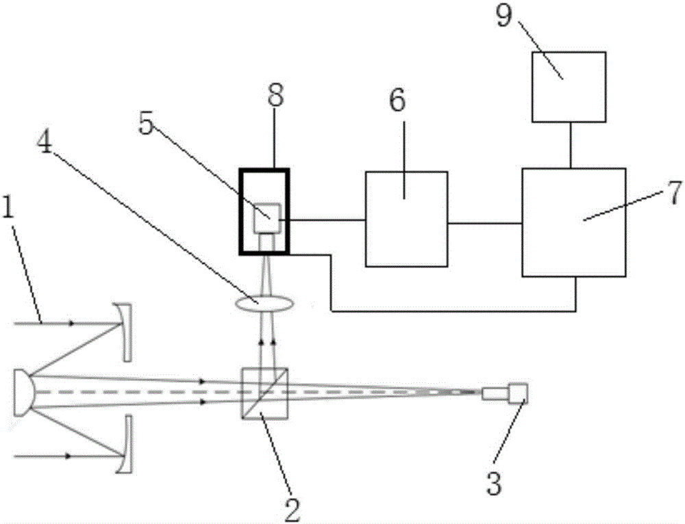
[0034] A light spot alignment method based on a four-quadrant detector in the present invention adopts a light beam detection device, such as figure 1 As shown, it includes a Cassegrain telescope 1, a dichroic prism 2 and a communication detector 3 arranged in sequence along the axis of the incident light beam. A lens 4 is arranged on one side of the dichroic prism 2, and a four-quadrant detector 5 is arranged behind the lens 4. The quadrant detector 5 is arranged on the pan-tilt 8 , and the four-quadrant detector 5 is connected to the amplification circuit 6 , the signal processing unit 7 and the display screen 9 in sequence, and the signal processing unit 7 is also connected to the pan-tilt 8 .

[0035] The signal processing unit 7 adopts an ARM processor of the Cotex-M3 series, and the ARM processor model is STM32F103ZET6. Amplifying circ...


PUM


Abstract

The invention discloses a light spot aligning method based on a four-quadrant detector. The light spot aligning method specifically comprises the following steps of focusing an incident beam onto a photo-sensitive surface of the four-quadrant detector by a lens, and enabling the four-quadrant detector to convert a received light signal into four paths of electric signals; amplifying the obtained four paths of electric signals by an amplifying circuit, transmitting the signals to the signal processing unit, and sequentially performing A / D (analog to digital) conversion and Kalman filtering on the four paths of amplified electric signals in the signal processing unit; performing self-adaptive threshold judging on the four paths of processed electric signals, controlling the action of a cradle head according to judging results, and enabling the cradle head to drive the four-quadrant detector to act, so as to adjust the position of the incident light beam, and align the incident light spot. The light spot aligning method solves the problem of difficulty in aligning of the light spot due to simultaneous existence of light spot drifting and malalignment between light beam and antenna visual axis.

Description

technical field [0001] The invention belongs to the technical field of wireless laser communication, and relates to a light spot alignment method based on a four-quadrant detector. Background technique [0002] In wireless laser communication, in order to establish and maintain a communication link, it is required that the transmitted beam is incident on the receiving surface vertically without offset. If the beam deviates and the communication link is interrupted, a beam pointing system is required to control the beam so that the communication transmitter and receiver are strictly aligned. The system that controls the beam pointing in the wireless laser communication system is called Acquisition, Pointing and Tracking (APT) system. Beam alignment is the key for APT system to establish and ensure reliable connection of communication link, and it is very important for Free Space Optical Communication (FSO) system. [0003] When the signal transmission distance is long, the ...

Claims


Application Information

Patent Timeline
Patent Type & Authority Applications(China)
IPC IPC(8): G01B11/26
CPCG01B11/26
Inventor 柯熙政王姣
Owner XIAN UNIV OF TECH
Learn More