Gas heater

A heater and gas technology, applied in household heating, lighting and heating equipment, household heating, etc., can solve problems such as poor airflow, achieve the effects of saving usage, avoiding poor airflow, and reducing emissions

Inactive Publication Date: 2018-09-28
宁波高新区新日立家电器有限公司
View PDF4 Cites 3 Cited by
  • Summary
  • Abstract
  • Description
  • Claims
  • Application Information

AI Technical Summary

Problems solved by technology

[0003] The purpose of the present invention is to provide a gas heater, which solves the problem that the existing gas heater is prone to poor air flow during use, ensures the combustion efficiency when the gas volume increases, and isolates the exhaust gas from the room to ensure personal safety

Method used


Image

  • Gas heater
  • Gas heater
  • Gas heater

Examples


Embodiment 1

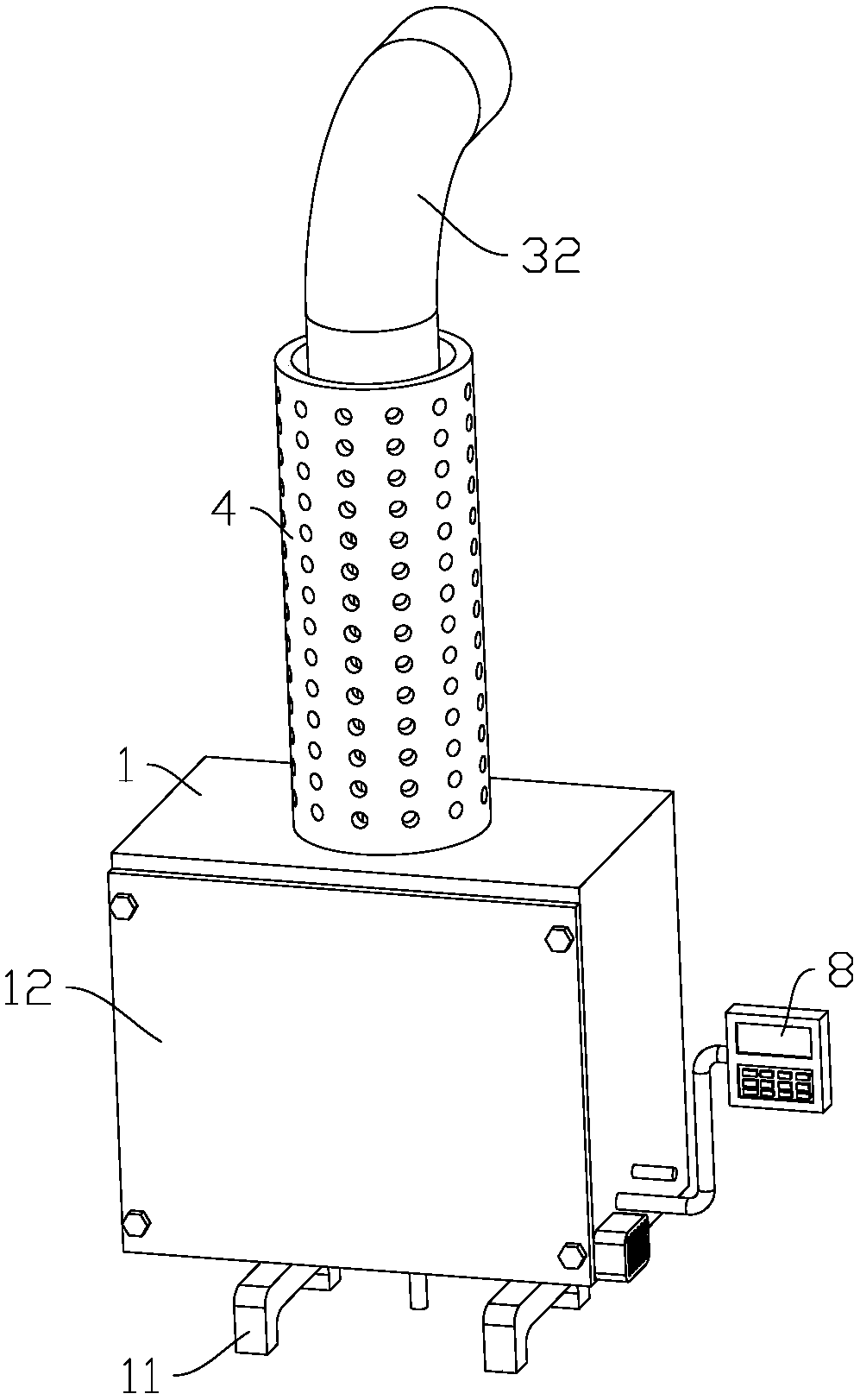
[0041] This embodiment discloses a gas heater, such as figure 1 As shown, it includes a housing 1 with an exhaust port, wherein the exhaust port is set upward to facilitate the exhaust gas to rise away from the housing 1, and the bottom of the housing 1 is detachably connected with several legs 11 to support the housing 1. In this embodiment Two legs 11 are provided, and a mounting opening is opened on one side of the housing 1 and a baffle 12 is detachably connected thereto.

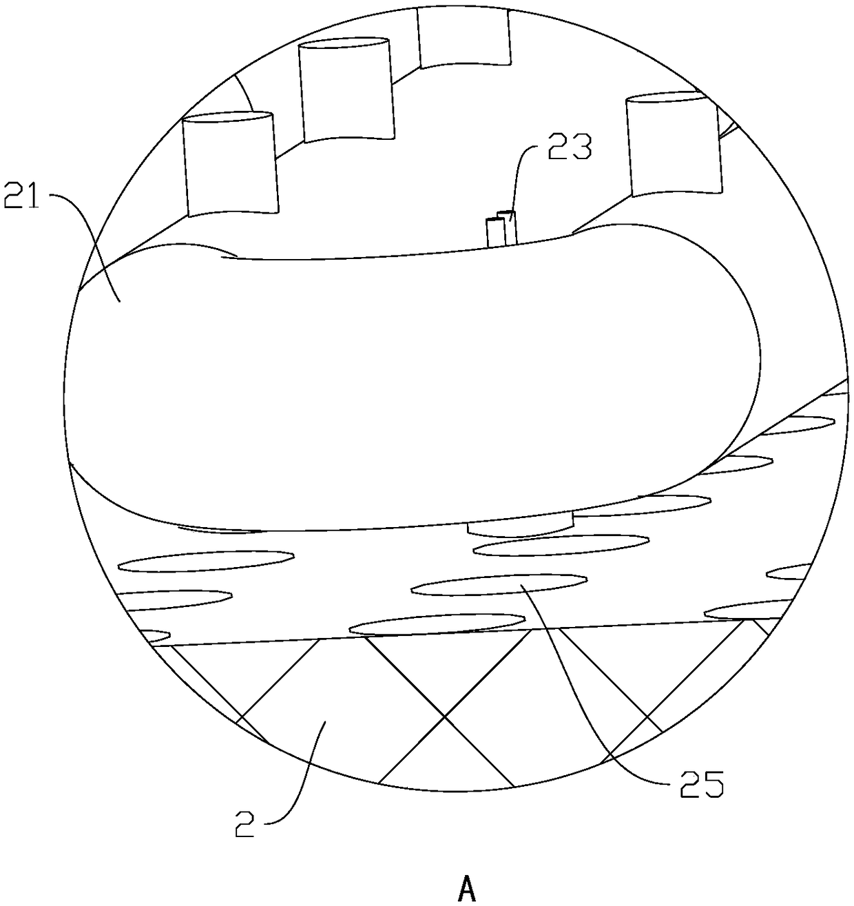
[0042] combine figure 2 , image 3 and Figure 4 , the housing 1 is provided with a combustion platform 2, the combustion platform 2 is detachably installed on the side of the housing 1 away from the installation port through screws, and there is a certain gap between the bottom of the housing 1, and the combustion platform 2 is installed with Fire row 21, intake pipe 22 for supplying gas and igniter 23; a cover body 3 is also clipped on the combustion platform 2 to divide the casing 1 into a cavity a...

Embodiment 2

[0052] This embodiment discloses a gas heater, which combines Figure 6 and Figure 8 The main difference from Embodiment 1 is that an inner tube 324 is arranged in the air duct 32, and the end of the air duct 32 away from the outdoor communicates with the combustion chamber, and the end of the inner tube 324 away from the outdoor runs through the side wall of the air duct 32 and communicates with the cavity. The inner side of the air duct 32 and the outer side of the inner tube 324 form a smoke exhaust channel 322, and the inner side of the inner tube 324 is an air intake channel 323. At this time, the outer wall of the air duct 32 is equidistantly arranged with a plurality of cooling tubes attached to the air duct 32. 5. The corresponding protective cover 4 is circumferentially provided with through holes 41 corresponding to the heat dissipation holes 51 of the heat dissipation pipe 5. In order to strengthen the structural stability of the inner pipe, a number of holes are w...


PUM


Abstract

The invention discloses a gas heater, and belongs to the technical field of heating equipment. The problems that an existing gas heater easily generates unsmooth air flow in the use process, and harmful gas is generated and threatens the life safety are solved. According to the technical scheme, the gas heater comprises a shell, a combustion platform is arranged in the shell, a fire grate, an airinlet pipe and an igniter are arranged on the combustion platform, an air guide pipe communicating with the outdoor position is further included, a cover body is arranged on the combustion platform, and a smoke discharge channel communicating with a combustion cavity and an air inlet channel communicating with a cavity are formed in the air guide pipe. According to the gas heater, when waste gas generated by combustion in the combustion cavity enters the smoke discharge channel, heat is transmitted to the indoor position, the outdoor air enters the cavity through the air inlet channel, and finally enters the combustion cavity to supply oxygen, when the gas amount is increased, the speed, passing through the air inlet channel, of outdoor air is correspondingly increased, oxygen can be supplied in time, the problem that the airflow is not smooth is avoided, and meanwhile, the waste gas is isolated from the indoor position to ensure life safety.

Description

technical field [0001] The invention relates to the technical field of heating equipment, in particular to a gas heater. Background technique [0002] Most gas heaters burn gas to release heat for heating. They have the advantages of cleanliness, high efficiency, and convenience, and have become the best equipment for outdoor or indoor heating. At present, in the commonly used indoor gas heaters on the market, the gas after combustion is directly discharged indoors for heating. Due to the low mobility of the indoor air, gas heaters are prone to the problem of poor air flow during use. When the gas volume increases , the combustion efficiency is not high, the exhaust channel often produces under-burned gas, including harmful gases such as carbon monoxide, which poses a certain threat to the human body, and at the same time, the inner wall of the exhaust channel accumulates carbon ash, which needs to be cleaned frequently, so there is still room for improvement . Contents o...

Claims


Application Information

Patent Timeline
Patent Type & Authority Applications(China)
IPC IPC(8): F24D15/02F24D19/10
CPCF24D15/02F24D19/1084
Inventor 周永胜
Owner 宁波高新区新日立家电器有限公司
Why Eureka
Try Eureka