U-shaped double-wall socket and spigot type pipe joint and installing method thereof

A pipe interface, socket-type technology, applied in the direction of sleeve/socket connection, pipe/pipe joint/pipe fitting, passing element, etc., can solve the problems such as the lack of positioning of the rubber sealing ring, the increase of the drainage pipe flow, and the pollution of groundwater sources. , to reduce the contact area, increase the service life, and achieve good seismic effect.

Inactive Publication Date: 2018-09-28
WISDRI ENG & RES INC LTD +1
View PDF9 Cites 7 Cited by
  • Summary
  • Abstract
  • Description
  • Claims
  • Application Information

AI Technical Summary

Problems solved by technology

It can be seen that the infiltration of groundwater is quite serious. A large amount of infiltration of groundwater will increase the flow of drainage pipes, increase the economic investment of sewage plants, and cause unnecessary losses to the national economy.
[0006] (2) Pollution of groundwater sources: Leakage of the sewage pipe interface will cause sewage leakage, and a large amount of ammonia nitrogen, nitrate, sulfate, organic matter, etc. will seep into the groundwater along with the sewage, causing the organic matter and inorganic salts in the groundwater to exceed the standard, seriously endangering the quality of the groundwater
[0010] (1) The rubber sealing ring is not positioned, the circumference of the rubber ring cannot guarantee a uniform compression ratio, and its sealing performance cannot be guaranteed, resulting in leakage;
[0011] (2) The depth of the socket joint cannot be precisely controlled, and the installation workers often determine the depth based on construction experience, which cannot guarantee that the socket is in place.
[0012] (3) The traditional socket interface relies on the friction between the socket and the socket to squeeze the rubber ring. Before the pipeline is backfilled, the water in the pipe ditch floats the pipe or the soil disturbance during backfilling will easily lead to the dislocation of the interface.

Method used


Image

  • U-shaped double-wall socket and spigot type pipe joint and installing method thereof
  • U-shaped double-wall socket and spigot type pipe joint and installing method thereof
  • U-shaped double-wall socket and spigot type pipe joint and installing method thereof

Examples


Embodiment

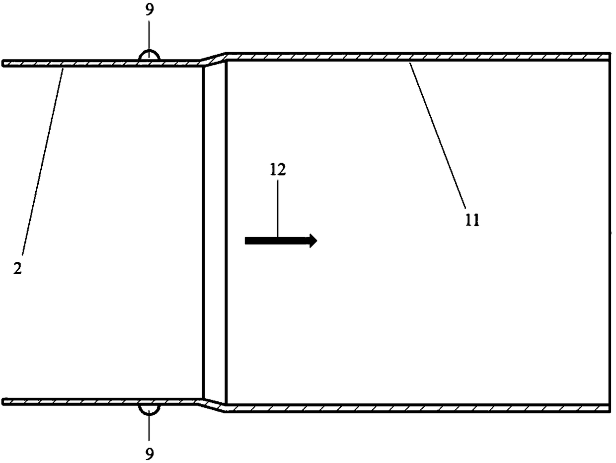
[0067] The U-shaped double-wall socket-type pipe joint of this embodiment is composed of three parts: a U-shaped double-wall socket end 1, a socket end 2 and a rubber sealing ring. The U-shaped slot 8 is formed by making the socket end 1 into a double-layer pipe wall, so that the width of the slot is consistent with the thickness of the pipe wall at the socket end 2. After installation, they fit together to form a good airtight performance; at the same time, the rubber seal The ring 4 is placed at the bottom of the U-shaped slot 8, and after being installed in place, the socket end 1 and the socket end 2 squeeze and compress the rubber sealing ring 4 to produce a double sealing effect. The inlet end of the inner side of the outer wall of the groove 5 is provided with a groove 7, which fits with the convex contact 9 on the outer wall of the socket end 2 during installation to form a lock to avoid axial slippage between the socket end 1 and the socket end 2. Strengthening ribs 3...


PUM


Abstract

The invention discloses a U-shaped double-wall socket and spigot type pipe joint and an installing method thereof. The U-shaped double-wall socket and spigot type pipe joint comprises a socket end anda spigot end. The socket end and the spigot end are used for being connected with the head and the tail of a common pipe section correspondingly to form a unit pipe section. The socket end is provided with a U-shaped slot formed by double layers of pipe walls. The spigot end is formed by a single layer of threadless round pipe wall. A buckle is arranged between the socket end and the spigot end.When pipe sections are connected in a sleeved mode, one spigot end is inserted in the corresponding U-shaped slot and is connected with the corresponding socket end through the corresponding buckle. The deficiency of a traditional plastic pipeline socket and spigot type joint is overcome, the anti-seismic effect is good, vertical rigidity is high, leakproofness is good, and installation is convenient and fast.

Description

technical field [0001] The invention relates to the technical field of drainage engineering pipelines, in particular to a U-shaped double-wall socket-type pipeline interface and an installation method thereof. Background technique [0002] With the rapid development of my country's economy, the country is gradually accelerating the construction of urban infrastructure, and the construction of drainage pipe network is one of the most important projects. The drainage system is the conscience of a city, and it is also an important supporting facility for urban municipal roads. The investment in the construction of pipe networks for urban transformation is also increasing year by year. At present, urban drainage pipe network projects generally include the construction of rainwater and sewage pipe networks in new urban areas, the renovation of rainwater and sewage pipe networks in old urban areas, and the construction of sponge city facilities. A good drainage pipe network syste...

Claims


Application Information

Patent Timeline
Patent Type & Authority Applications(China)
IPC IPC(8): F16L21/08F16L21/04
CPCF16L21/04F16L21/08
Inventor 赵开拓
Owner WISDRI ENG & RES INC LTD
Why Eureka
Try Eureka