Gum dipping device for capsule production line

A production line and glue dipping technology, which is applied in capsule delivery, drug delivery, and pharmaceutical formulations, etc., can solve the problems of varying capsule disintegration time, complex structure of the glue dipping device, and poor overall stability, achieving high glue dipping efficiency, Time and effort saving, structurally stable effect

Inactive Publication Date: 2018-09-25
苏州高新区鼎正精密机电有限公司
View PDF7 Cites 0 Cited by
  • Summary
  • Abstract
  • Description
  • Claims
  • Application Information

AI Technical Summary

Problems solved by technology

[0004] The purpose of the present invention is to solve the problems in the prior art that the disintegration time of capsules is different, and the structure of the dipping device is complex, the overall stability is poor, the operation is cumbersome, time-consuming, laborious, low production efficiency, and low efficiency of dipping the glue. A glue dipping device for a capsule production line, and a glue dipping device for a fully automatic capsule production line

Method used


Image

  • Gum dipping device for capsule production line
  • Gum dipping device for capsule production line
  • Gum dipping device for capsule production line

Examples


Embodiment 1

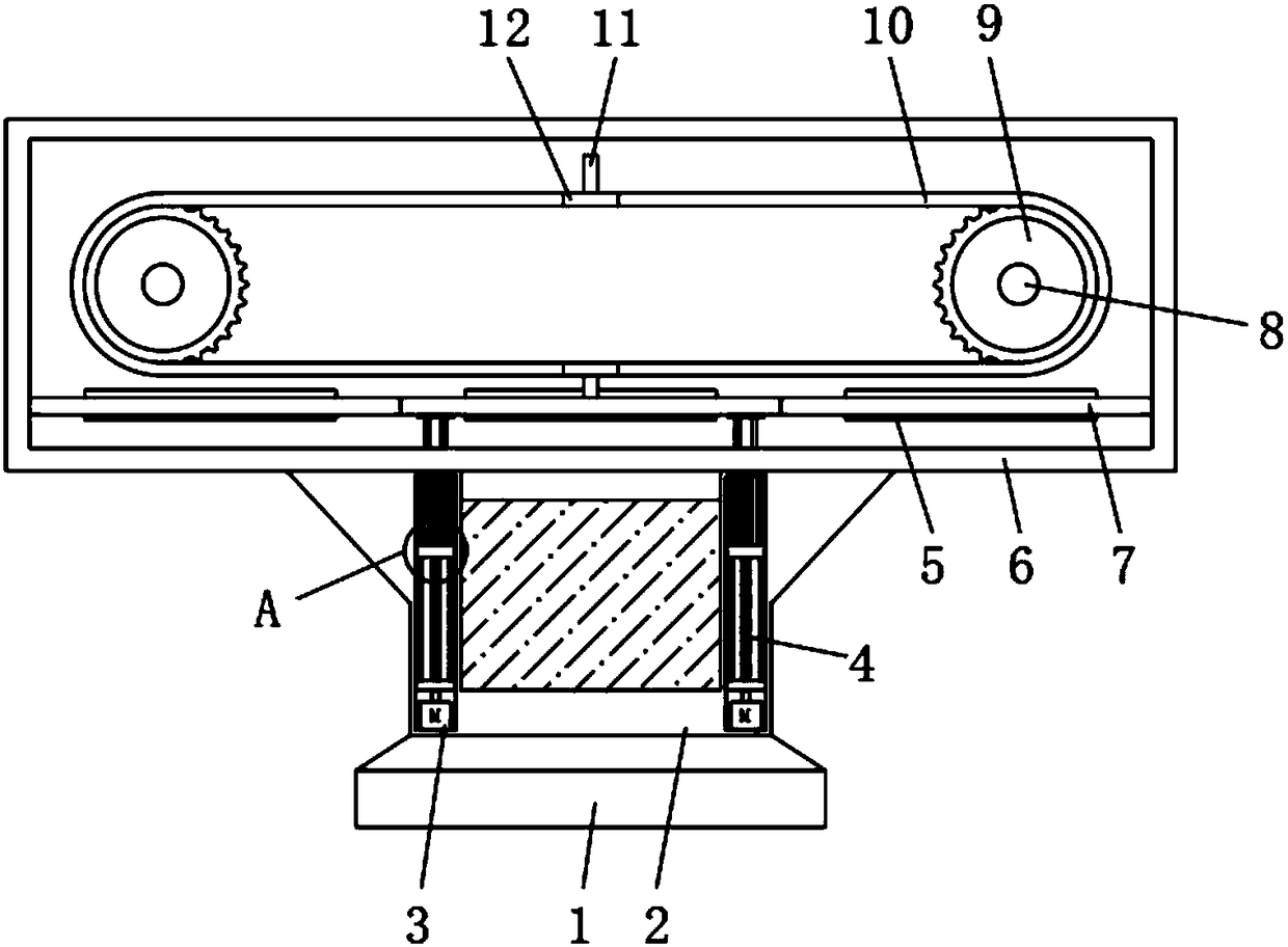
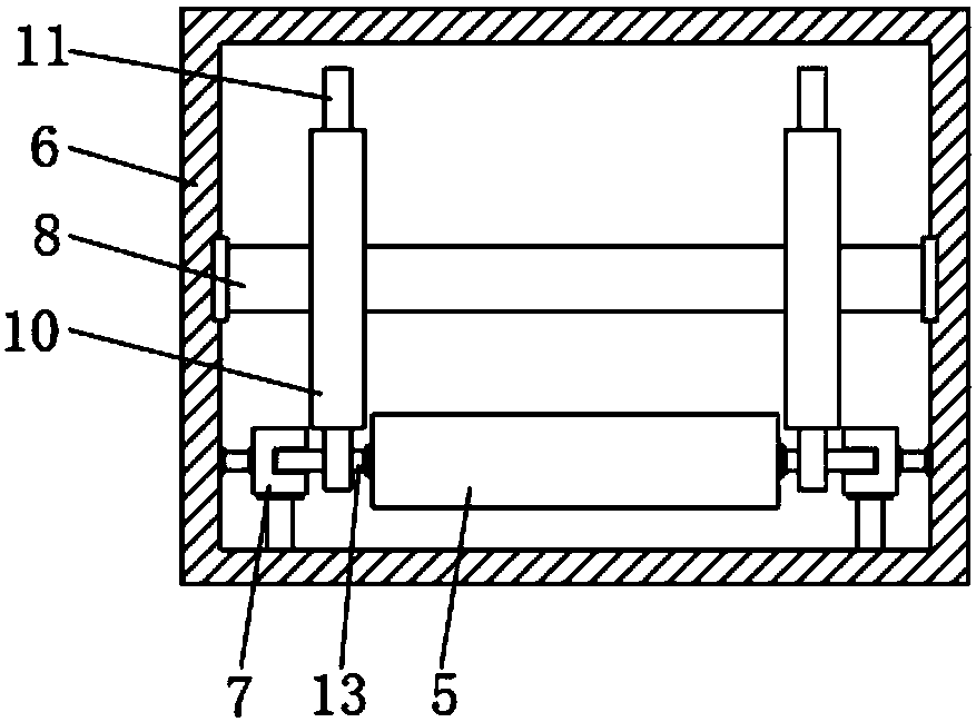
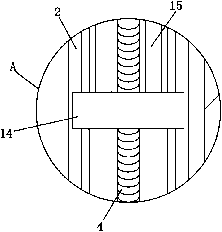
[0026] Embodiment 1: with reference to Figure 1-3 , the dipping device of the automatic capsule production line, including a base 1, the upper end of the base 1 is provided with a storage barrel 2 for placing liquid, and the upper end of the storage barrel 2 is fixedly connected with a protective cover 6, and the protective cover 6 is symmetrically rotated and connected with Two rotating shafts 8, each rotating shaft 8 is equipped with a gear 9 symmetrically, and the gear 9 on the same side of the two rotating shafts 8 is provided with a chain 10, and each chain 10 is provided with two moving blocks 12, Each moving block 12 has the same structure as the chain 10; the side of each moving block 12 away from the gear 9 is provided with a driving lever 11, which is used to make the placement frame 5 move on the sliding rod 7, and the driving rod 11 is located on the sliding rod 7 Between the shelf 5 and the side wall of the protective cover 6, two sliding rods 7 are symmetrically...

Embodiment 2

[0032] Embodiment 2: The performances of Embodiment 1 and commercially available common capsule shells were tested, and the obtained data are shown in the table below.

[0033] 1. Determination of transparency: the sample’s internal light reflection factor and the difference between the light reflection factor and the percentage of the internal light reflection factor are measured with a whiteness meter. The method refers to QB / T1913-2004.

[0034] 2. Measurement of softness: measured with a Shore hardness tester.

[0035] group

[0036] It can be seen from the above results that the capsule shell of the present invention can improve the weather resistance of the capsule shell, and when the drug effect is guaranteed at low temperature, it does not affect the life of the capsule shell and widens the scope of use of the capsule shell.


PUM


Abstract

The invention discloses a gum dipping device for a capsule production line. The device comprises a base, wherein a accommodating barrel is arranged at the upper end of the base, a protective cover isfixedly connected to the upper end of the accommodating barrel, two rotating shafts are symmetrically and rotationally connected in the protective cover, each rotating shaft is sleeved with gears symmetrically, the gears on the same sides of the two rotating shafts are commonly sleeved with a chain, two moving blocks are arranged on each chain, and a shifting rod is arranged on the side, away fromthe corresponding gear, of each moving block; two sliding rods are symmetrically arranged on the side wall of the protective cover, two support rods are symmetrically and glidingly connected to eachsliding rod, and an accommodating frame is fixedly connected with the ends, away from the sliding rods, of the two support rods. The device is stable in structure, easy to operate, scientific and reasonable in design, short in production period, low in production cost, good in shock-proof performance, high in production efficiency, high in gum dipping efficiency and capable of saving a large amount of time and energy of workers.

Description

technical field [0001] The invention relates to the technical field of capsule production, in particular to a glue dipping device for a fully automatic capsule production line. Background technique [0002] Empty capsules mostly use animal gelatin as the main raw material, and the source of animal gelatin is mostly fermented from animal skin and bone, and a large amount of chemical components are added during the fermentation process, which will cause serious pollution to the air and water environment. In addition, most of the existing vegetable capsules use one or more of K-type carrageenan, gellan gum, konjac gum, xanthan gum, etc. Dispenses quick-release medications. [0003] In addition, the existing glue dipping devices generally include dipping glue hangers, glue dipping molds, glue dipping tanks and other components. The lifting of the hanger makes the dipping mold dip into the glue in the dipping tank to complete the dipping process, and then the dipping mold is tr...

Claims


Application Information

Patent Timeline
Patent Type & Authority Applications(China)
IPC IPC(8): A61J3/07
CPCA61J3/077
Inventor 孙芳良
Owner 苏州高新区鼎正精密机电有限公司
Why Eureka
Try Eureka