Catalyst layer used for fuel cell
A fuel cell and catalyst layer technology, which is applied to battery electrodes, circuits, electrical components, etc., can solve the problems of incomplete fuel conversion, incomplete CO reaction, and reduced electrode performance, so as to improve electrode performance, prolong residence time, Avoid poisoning effects
- Summary
- Abstract
- Description
- Claims
- Application Information
AI Technical Summary
Problems solved by technology
Method used
Image

Examples
Embodiment 1
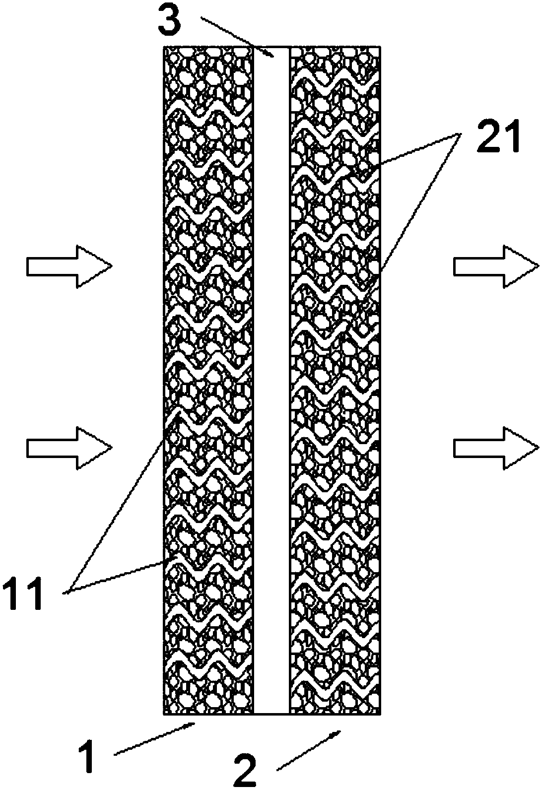
[0029] Embodiment 1, as attached figure 2 As shown, a catalyst layer for a fuel cell includes an initial reaction layer 1, a deep reaction layer 2, a fuel channel one 11, and a fuel channel two 21; the initial reaction layer 1 is arranged on one side of the deep reaction layer 2, specifically Yes, the initial reaction layer 1 is arranged on one side of the deep reaction layer 2 feeding direction;
[0030] A plurality of the first fuel channels 11 are equidistantly arranged in the initial reaction layer 1, and a plurality of fuel channels 2 21 are arranged in the deep reaction layer 2; and the first fuel channels 11 and The two fuel passages 21 are alternately arranged; the initial reaction layer 1 and the deep reaction layer 2 are also communicated with a rectification area 3, and the rectification area 3 is mainly for the primary reaction of the fuel. The CO is fully rectified and mixed, and the next step of deep reaction work is performed again, which can effectively make ...
Embodiment 2
[0034] Embodiment 2, the fuel channel one and the fuel channel two can also be broken lines, serpentine structures, etc.; the width of the initial reaction layer is 1.2 cm, the width of the deep reaction layer is 0.9 cm, and the width of the rectification area 1 / 3 of the width of the initial reaction layer. The final detection fuel reaction degree is: the obtained H 2 The mass fraction content is 78% of the tested substance, and the CO mass fraction content is 0.01% of the tested substance.
Embodiment 3
[0035] Example 3, the width of the initial reaction layer is 1.1 cm, the width of the deep reaction layer is 0.85 cm, and the width of the rectification zone is 1 / 3 of the width of the initial reaction layer. The final detection fuel reaction degree is: the obtained H 2 The mass fraction content is 73% of the detected substance, and the CO mass fraction content is 0.02% of the detected substance.
[0036] The final data shows that in Example 2, when the width of the initial reaction layer is 1.2cm, the width of the deep reaction layer is 0.9cm, and the width of the rectification zone is 1 / 3 of the width of the initial reaction layer, the obtained H 2 The mass fraction content is the most ideal, and the CO reaction is relatively thorough.
[0037] The beneficial effects of the present invention are: (1) the present invention realizes complete conversion of fuel, complete reaction of CO, avoids poisoning caused by long-term residual existence of CO, and further improves electro...
PUM
| Property | Measurement | Unit |
|---|---|---|
| Width | aaaaa | aaaaa |
| Width | aaaaa | aaaaa |
| Width | aaaaa | aaaaa |
Abstract
Description
Claims
Application Information
 - Generate Ideas
- Intellectual Property
- Life Sciences
- Materials
- Tech Scout
- Unparalleled Data Quality
- Higher Quality Content
- 60% Fewer Hallucinations
Browse by: Latest US Patents, China's latest patents, Technical Efficacy Thesaurus, Application Domain, Technology Topic, Popular Technical Reports.
© 2025 PatSnap. All rights reserved.Legal|Privacy policy|Modern Slavery Act Transparency Statement|Sitemap|About US| Contact US: help@patsnap.com