
Machine tool for processing wafer surface

A technology of surface processing and machine tools, which is applied in the direction of electrical components, semiconductor/solid-state device manufacturing, circuits, etc., and can solve problems such as unfavorable popularization, damage to wafers loaded, and reduced production efficiency

Active Publication Date: 2018-09-18
游精学
View PDF5 Cites 3 Cited by
  • Summary
  • Abstract
  • Description
  • Claims
  • Application Information

AI Technical Summary

Problems solved by technology

[0003] It is not difficult to see that although this prior art can better solve the technical problem of weak and fragile thin wafer wafers, it additionally increases the loading wafer, which not only increases the process, reduces the production efficiency, but also increases the production efficiency of the wafer. Most of the wafers use engineering plastic boards, which are discarded directly after the functional wafers are cut. Therefore, the above-mentioned carrier wafers as one-time consumables will obviously lead to an increase in processing costs, which is not conducive to the popularization of mass production.
[0004] In addition, there are carrier wafers that can be recycled many times in the prior art, but the functional wafers and the carrier wafers in the prior art are bonded by bonding glue, so there are many problems in the process of removing the bonding glue. It is removed by chemical cleaning agent, mechanical stripping or local high temperature laser, etc. Obviously, the debonding process of these existing technologies will cause a certain degree of damage to the carrier wafer, so this kind of carrier wafer that can be recycled many times There is also a great limit to the number of times it can be used, so there is also the problem of high processing costs
[0005] It is not difficult to see that for the thin wafer processing of the prior art, the debonding process is the core technical problem that limits its production efficiency, product yield improvement and cost reduction

Method used


Image

  • Machine tool for processing wafer surface
  • Machine tool for processing wafer surface
  • Machine tool for processing wafer surface

Examples


Embodiment 1

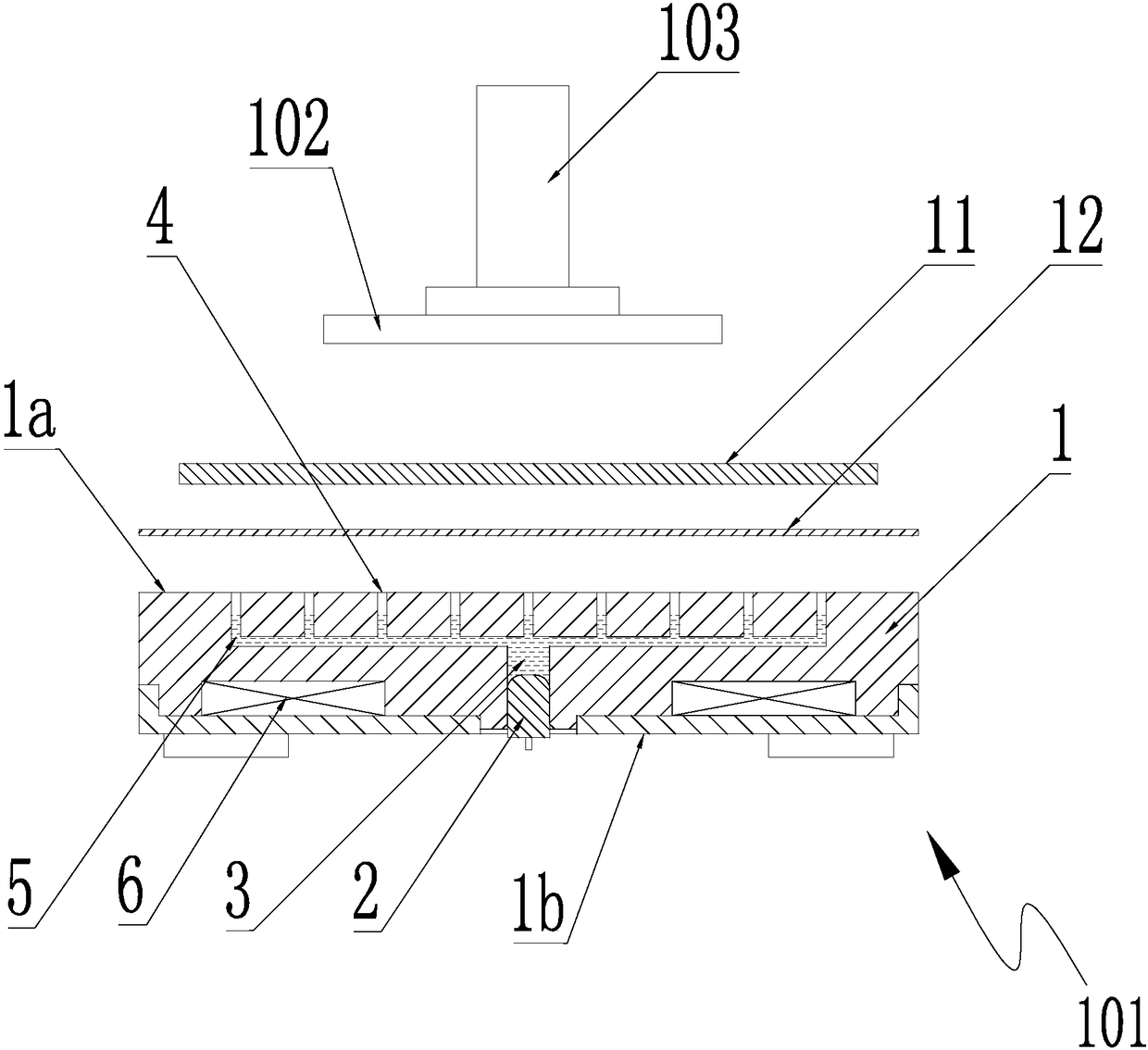
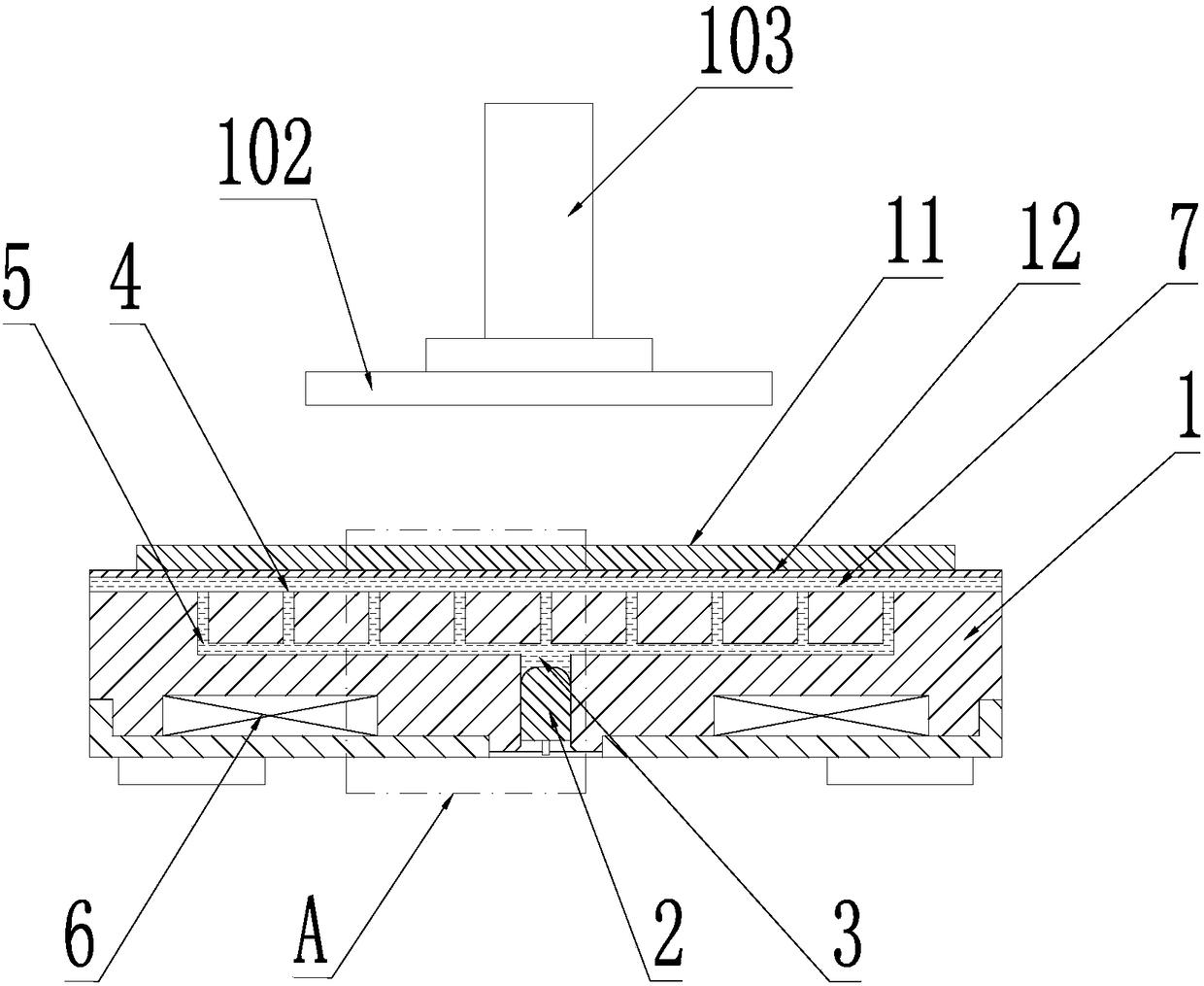
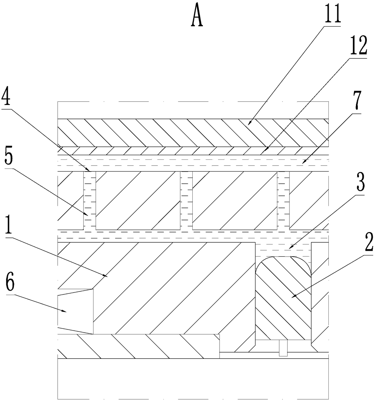
[0035] As a preference, the above-mentioned plug 2 is provided with a slot 2.1, a connecting pipe 2.2 and a pressure relief pipe 2.3, the upper end of the connecting pipe 2.2 communicates with the liquid storage chamber 3, and the lower end of the pressure relief pipe 2.3 runs through the plug 2 The lower end surface of the connecting pipe 2.2 communicates with the space outside the base body 1, the lower end of the connecting pipe 2.2 and the upper end of the pressure relief pipe 2.3 communicate with the slot 2.1, and a valve plate 8 is arranged in the slot 2.1, and the valve plate 8 Move along the groove depth direction of the slot 2.1 to make the connecting pipe 2.2 communicate with or disconnect from the pressure relief pipe 2.3. As shown in the figure, the above-mentioned groove depth direction is the vertical direction shown in the figure, and it is also the length direction of the plug 2 or the thickness direction of the base body 1 .

Embodiment 2

[0037] The general structure is the same as that of Embodiment 1, the difference is that the lower end of the connecting pipe 2.2 communicates with the groove bottom of the slot 2.1 along the length direction of the plug 2, and the upper end of the pressure relief pipe 2.3 connects with the bottom of the slot 2.1 along the horizontal direction. The side wall communicates with the position close to the groove bottom.

Embodiment 3

[0039] The general structure is the same as that of the second embodiment, except that the bottom of the slot 2.1 is inscribed upward along the length direction of the plug 2 to form an annular groove 2.4. The setting of the annular groove 2.4 can make air remain in the annular groove 2.4, and the compressibility of the air is used to make the load force of the valve plate at the initial stage of pulling out small, which is convenient for the valve plate to be pulled out.


PUM


Abstract

The invention discloses a machine tool for processing a wafer surface. The machine tool comprises a workpiece mounting table and a carrier which is detachably mounted on the workpiece mounting table.A millstone is arranged above the carrier. The millstone is mounted on the driving shaft of the machine tool and rotates along with the driving shaft of the machine tool. The millstone comprises a disc-shaped body. The central position of the lower end surface of the body is provided with a mounting trough. The mounting trough is internally provided with a sub-millstone. The lower end surface of the body is provided with a plurality of liquid feeding troughs which are uniformly distributed along the circumferential direction of the mounting trough. The liquid feeding troughs are used for accommodating mortar. In the inner wall of the liquid feeding trough, an inside wall which corresponds with the opposite direction of a body rotation direction is in transition connection with the lower end surface of the body. The machine tool for processing the wafer surface can satisfy a requirement for strength after wafer bonding and furthermore realizes quick and reliable wafer de-bonding process. The machine tool has advantages of high efficiency, high product qualified rate and low processing cost.

Description

technical field [0001] The invention relates to the technical field of wafer processing, in particular to a machine tool for wafer surface processing. Background technique [0002] Thin wafers, especially thin wafers with a thickness less than 5mm, often need to be temporarily bonded to a carrier wafer during processing, so as to improve the strength of the functional wafer and facilitate processing, such as Thinning and grinding, etching, cutting, etc., and finally the functional wafer and the carrier wafer are separated to complete the processing of the functional wafer. [0003] It is not difficult to see that although this prior art can better solve the technical problem of weak and fragile thin wafer wafers, it additionally increases the loading wafer, which not only increases the process, reduces the production efficiency, but also increases the production efficiency of the wafer. Most of the wafers use engineering plastic boards, which are discarded directly after th...

Claims


Application Information

Patent Timeline
IPC IPC(8): H01L21/67
CPCH01L21/67005H01L21/67092
Inventor 韩赛
Owner 游精学
Learn More