Heat storage system

A heat storage system and heat storage brick technology are applied in the field of heating equipment, which can solve the problems of back-cooling, unfavorable promotion and application of heating equipment, and no energy saving, and achieve the effects of reducing use costs, facilitating promotion and application, and reducing loss.

Pending Publication Date: 2018-09-14
ZHEJIANG GIANT TECH CO LTD
View PDF7 Cites 0 Cited by
  • Summary
  • Abstract
  • Description
  • Claims
  • Application Information

AI Technical Summary

Problems solved by technology

[0003] The common heating equipment on the market is radiator heating. When the heat medium such as water flows through the radiator, the heat carried by the heat medium is continuously transferred to the object with a lower temperature through the radiator fin, so as to realize the temperature difference transfer of heat energy. This kind of radiator is bulky and most of them are integrally formed. The temperature of the radiator will reach the same temperature as the hot coal in the pipe at most, and will not exceed the temperature of the hot coal. In practice, the radiator needs to dissipate heat to the surrounding space, so it will not reach The temperature of the hot water in the water pipe below, the inlet temperature of the radiator is higher than the outlet temperature, and there is a relatively large energy loss on the way of hot coal being transported from the pipeline to the radiator
And another kind of electric heater is to use the electric heating tube to heat after being energized, and the moment when the electric energy is converted into heat energy, the heat is transferred and released into the air. The power is adjusted by increasing or decreasing the number of electric heating tubes connected. The temperature rises slowly, cannot store heat, consumes a lot of electricity, and lasts for a long time. After the power is cut off, the room will cool down soon; Power to achieve, power consumption and not energy-saving
[0004] In the existing thermal cycle system, because the temperature difference between the furnace body and the furnace body cannot be sensed, the fan will continue to run at the same frequency, resulting in large energy consumption and high cost of use, which is not conducive to the application of heating equipment in the field of family life. Promotion and application

Method used


Image

  • Heat storage system
  • Heat storage system
  • Heat storage system

Examples


Embodiment

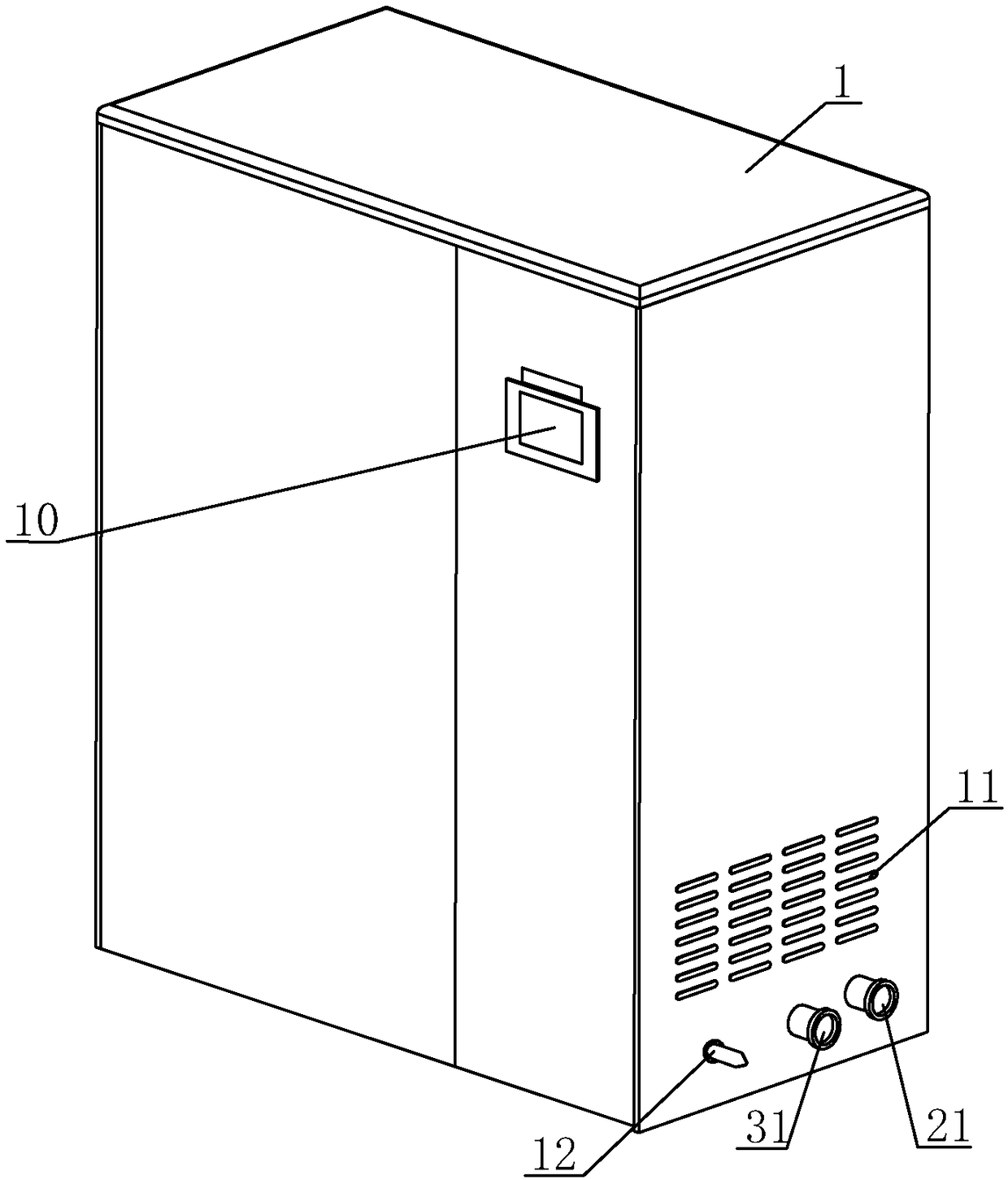
[0026] Example: such as Figure 1 to Figure 5 As shown, the heat storage system includes a hot furnace body and a hot air circulation system. The main components of the above hot air circulation system are installed in the above hot furnace body to reduce the speed of heat loss.

[0027] The furnace body includes a shell 1 with a cavity inside, and an electric controller is set inside the shell 1. The hot air circulation system includes a circulating fan 8, a heat storage device and a heat exchanger 7. The electric controller is provided with a program to control the circulating fan. 8 and heat exchanger 7 and other equipment, the shell 1 is provided with a temperature probe 12 for detecting the temperature difference between the inner and outer temperature of the furnace, the above-mentioned temperature probe 12 and the above-mentioned circulating fan 8 are all connected to the electric controller, The signal on the needle 12 is transmitted to the electric controller, and the...


PUM


Abstract

The invention relates to a heat storage system. The heat storage system comprises a heat furnace body and a hot air circulation system, wherein the hot air circulation system is arranged inside the heat furnace body; the heat furnace body comprises a shell, and an electric controller is arranged inside the shell; the hot air circulation system comprises a circulating fan, a heat storage device anda heat exchanger, wherein the heat storage device comprises electric heating pipes and heat storage bricks, and electric conductors with an sectional area larger than the sectional area of the electric heating pipes are arranged on the electric heating pipes; a water inlet and a water outlet are formed in the heat exchanger, the water inlet is connected with a water inlet pipe, and the water inlet pipe is connected with a circulating water pump, the water outlet is connected with a water outlet pipe, the water outlet pipe is connected with a heat dissipation device, and the water inlet pipe communicates with the water outlet pipe; the shell is provided with a temperature probe, and the temperature probe and the circulating fan are connected with the electric controller correspondingly. The external circulating water pump and the heat dissipation device is connected through the water inlet and outlet of the heat exchanger by the heat storage system, the heating effect can be achieved in a short time, the electric quantity loss is reduced, the use cost is reduced, and the popularization and application of the heating equipment are facilitated in the market.

Description

technical field [0001] The invention relates to the technical field of heating equipment, in particular to a heat storage system. Background technique [0002] With global climate variability and population density increasing, how to save energy and reduce emissions has become the focus of human attention. And improving the utilization rate of heating equipment is also a major improvement point of energy conservation. [0003] The common heating equipment on the market is radiator heating. When the heat medium such as water flows through the radiator, the heat carried by the heat medium is continuously transferred to the object with a lower temperature through the radiator fin, so as to realize the temperature difference transfer of heat energy. This kind of radiator is bulky and most of them are integrally formed. The temperature of the radiator will reach the same temperature as the hot coal in the pipe at most, and will not exceed the temperature of the hot coal. In prac...

Claims


Application Information

Patent Timeline
Patent Type & Authority Applications(China)
IPC IPC(8): F24D11/00F24D19/10
CPCF24D11/004F24D19/1096F24D2200/08F24D2220/042
Inventor 闵大伟
Owner ZHEJIANG GIANT TECH CO LTD
Why Eureka
Try Eureka