
Petroleum barrel cleaning equipment for petroleum refining

A technology for cleaning equipment and oil drums, which is applied to the field of oil drum cleaning equipment for petroleum refining, can solve the problems of reduced impact force of water flow, easy to wear rods, waste of water resources, and work efficiency, so as to improve the driving force, improve work efficiency, Optimizing the effect of the internal pressurization structure

Inactive Publication Date: 2018-09-14
王维维
View PDF0 Cites 1 Cited by
  • Summary
  • Abstract
  • Description
  • Claims
  • Application Information

AI Technical Summary

Problems solved by technology

[0003] Aiming at the deficiencies in the prior art, the object of the present invention is to provide an oil barrel cleaning equipment for oil refining, to solve the water cleaning of the oil barrel cleaning equipment, generally use the pressurized effect for cleaning, and the piston cylinder push cleaning is the first choice. However, the reciprocating movement of the piston is easy to wear the rod, and the long-term reciprocating movement of the piston will easily cause a gap with the piston cylinder of the matching product. When pressurized, oil will leak, and parts need to be replaced regularly. The continued use of the supercharged structure after wear and tear will cause The impact force of the water flow is reduced, which wastes water resources and reduces work efficiency.

Method used


Image

  • Petroleum barrel cleaning equipment for petroleum refining
  • Petroleum barrel cleaning equipment for petroleum refining
  • Petroleum barrel cleaning equipment for petroleum refining

Examples


Embodiment Construction

[0024] In order to make the technical means, creative features, goals and effects achieved by the present invention easy to understand, the present invention will be further described below in conjunction with specific embodiments.

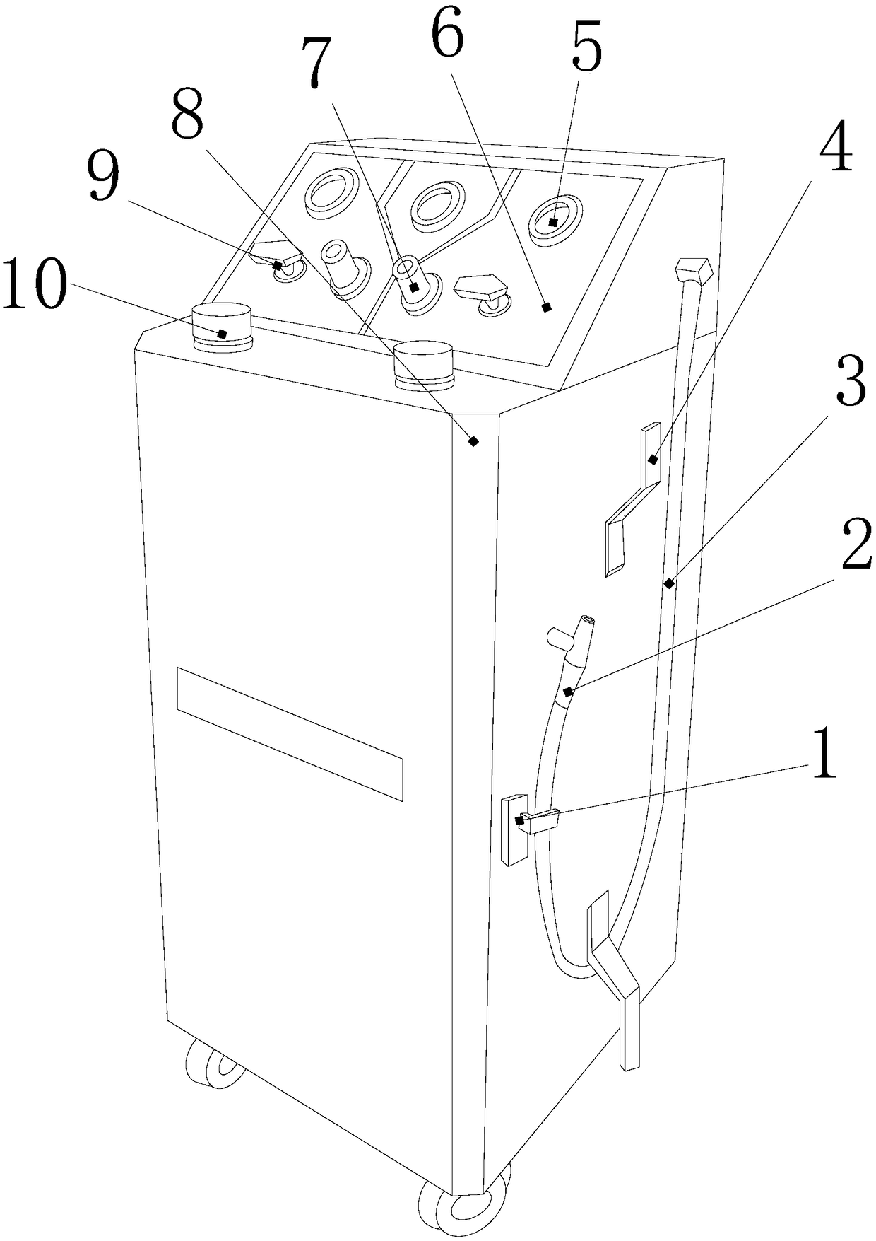
[0025] see Figure 1-Figure 5 , the present invention provides a kind of oil barrel cleaning equipment for petroleum refining, its structure includes: curved splint 1, water gun nozzle 2, water delivery conduit 3, Z-shaped hanging plate 4, pressure gauge 5, main control console 6, rocker Column cylinder 7, pumped tube type air compressor box 8, switch handle 9, adjustment knob 10, the top surface of the pumped tube type air compressor box 8 is closely attached to the bottom surface of the main control console 6 and communicates with each other. The pressure gauge 5 is nested on the front side of the main control console 6 at an angle of forty-five degrees. The rod cylinder 7 is inserted and embedded in the front side of the main control console 6...


PUM


Abstract

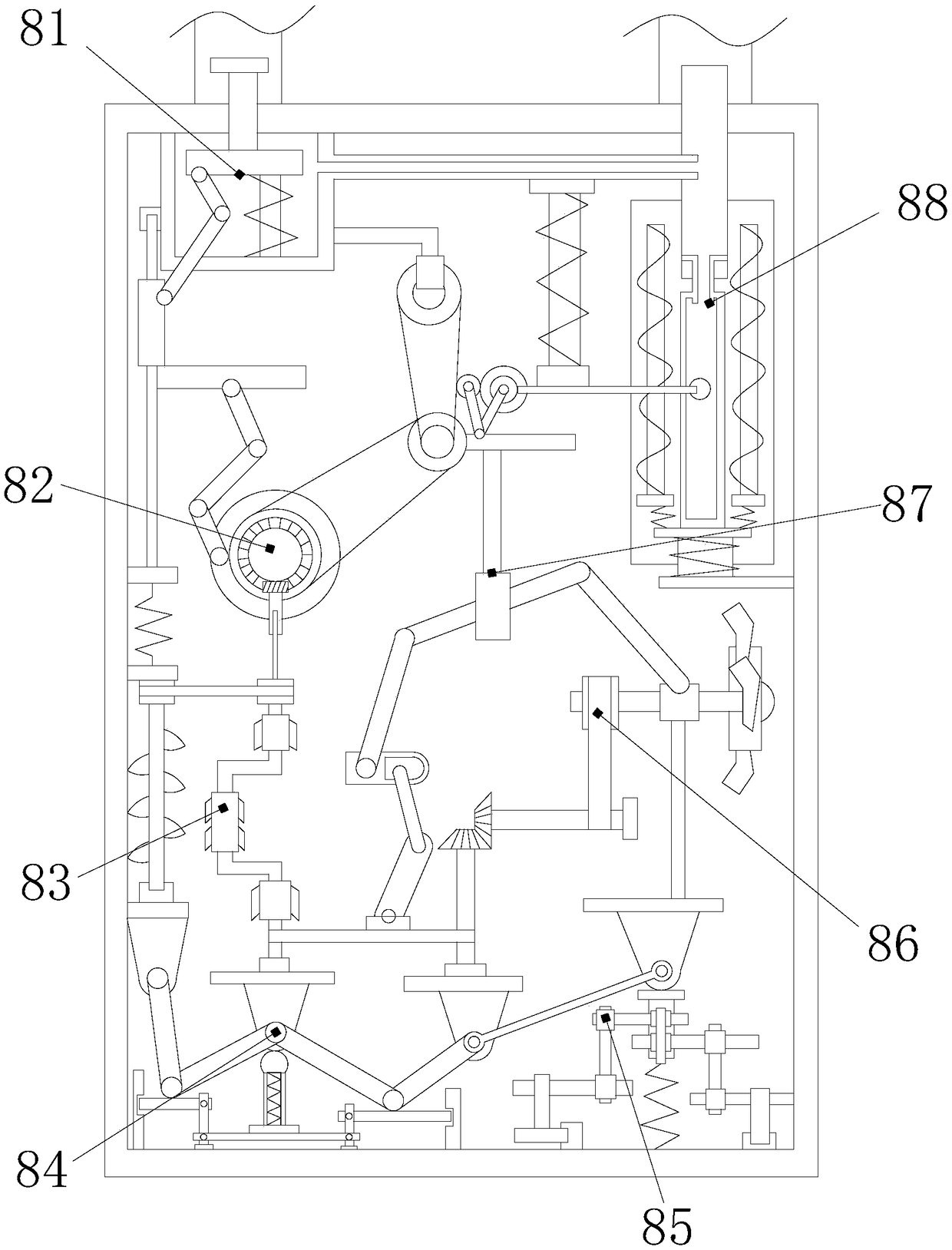
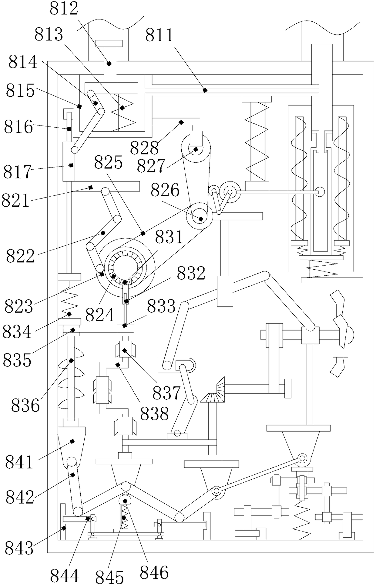
The invention discloses petroleum barrel cleaning equipment for petroleum refining. The equipment comprises a bent buckle clamping plate, a water gun nozzle, a water conveying guide pipe, a Z-shaped hanging plate, a pressure gauge, a main control console, a rocking rod column cylinder, an extracting pipe air pressure box, a switch holding handle and an adjusting knob; the top surface of the extracting pipe air pressure box is tightly bonded below the bottom surface of the main control console, and communicates with the same; the extracting pipe air pressure box is provided with a pushing device, a roller mechanism, a rotating device, a clamping plate bracket, a buckle rod chassis, a turbine mechanism, a connecting rod lifting frame and an extracting pipe mechanism, and achieves an effect of the petroleum barrel cleaning equipment using air pressure for water current pressurized outputting to form the air pressure contrast inside and outside the box, so that the efficient operation of atransmission structure in the box and the turbine supercharging effect are influenced, water currents are promoted to fully scour petroleum barrels, meanwhile, the working efficiency is improved, andthe loss condition has no needed to be worried after continuous use; and the air pressure is converted to mechanical energy for outputting by applying kinetic energy conservation, so that the internal supercharging structure is optimized, and the motive power of equipment cleaning actions is improved.

Description

technical field [0001] The invention relates to oil barrel cleaning equipment for oil refining, which belongs to the field of oil refining and oil barrel cleaning equipment. Background technique [0002] Petroleum, one of the main objects of geological exploration, is a viscous, dark brown liquid known as "industrial blood". There are oil reserves in some areas of the upper crust, and the main components are various alkanes, cycloalkanes, and aromatic hydrocarbons The oil-forming mechanism of petroleum has two theories of biosedimentary oil and petrochemical oil. The former is more widely accepted. It is believed that oil is formed by organisms in ancient oceans or lakes after a long evolution. It belongs to biosedimentary oil and is non-renewable. The latter believes that petroleum is produced by the carbon in the earth's crust itself, has nothing to do with biology, and is renewable. Petroleum is mainly used as fuel oil and gasoline, and is also a raw material for many che...

Claims


Application Information

Patent Timeline
Patent Type & Authority Applications(China)
IPC IPC(8): B08B9/093B08B13/00
CPCB08B9/093B08B13/00B08B2209/08
Inventor 王维维
Owner 王维维
Learn More