Measuring instrument supporting device
A technology for supporting devices and measuring instruments, applied in the directions of measuring devices, measuring instruments, measuring instrument components, etc., can solve the problems of inconvenience and large size, and achieve the effect of being easy to carry, small in size and reducing height
- Summary
- Abstract
- Description
- Claims
- Application Information
AI Technical Summary
Problems solved by technology
Method used
Image
Examples
Embodiment 1
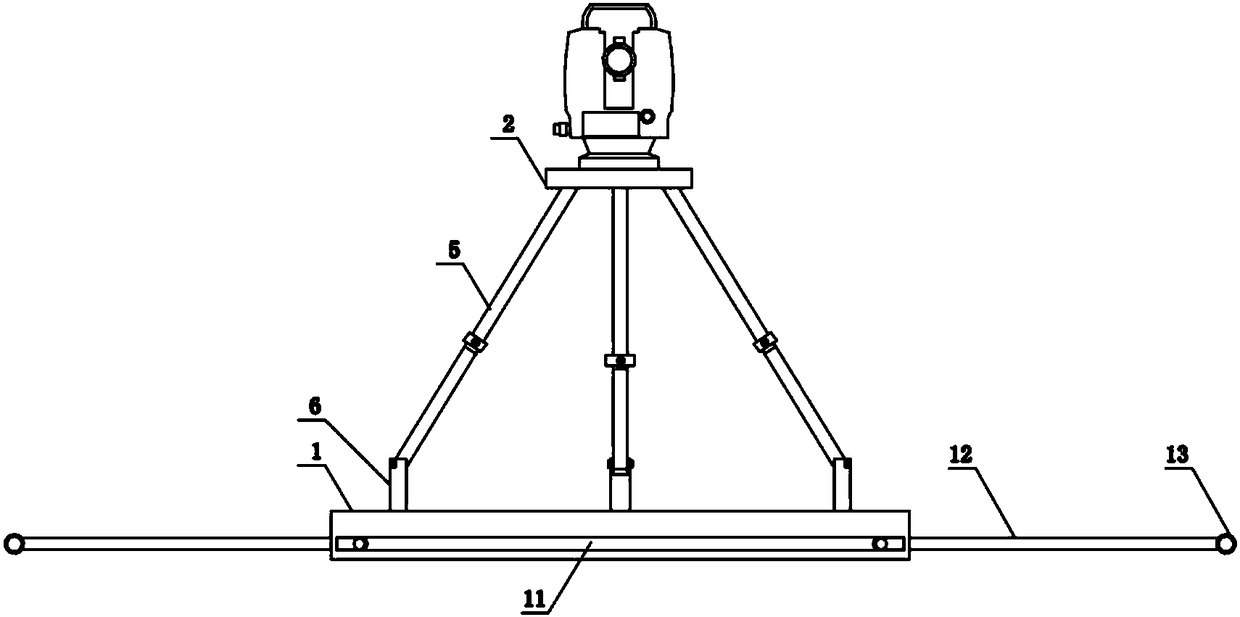
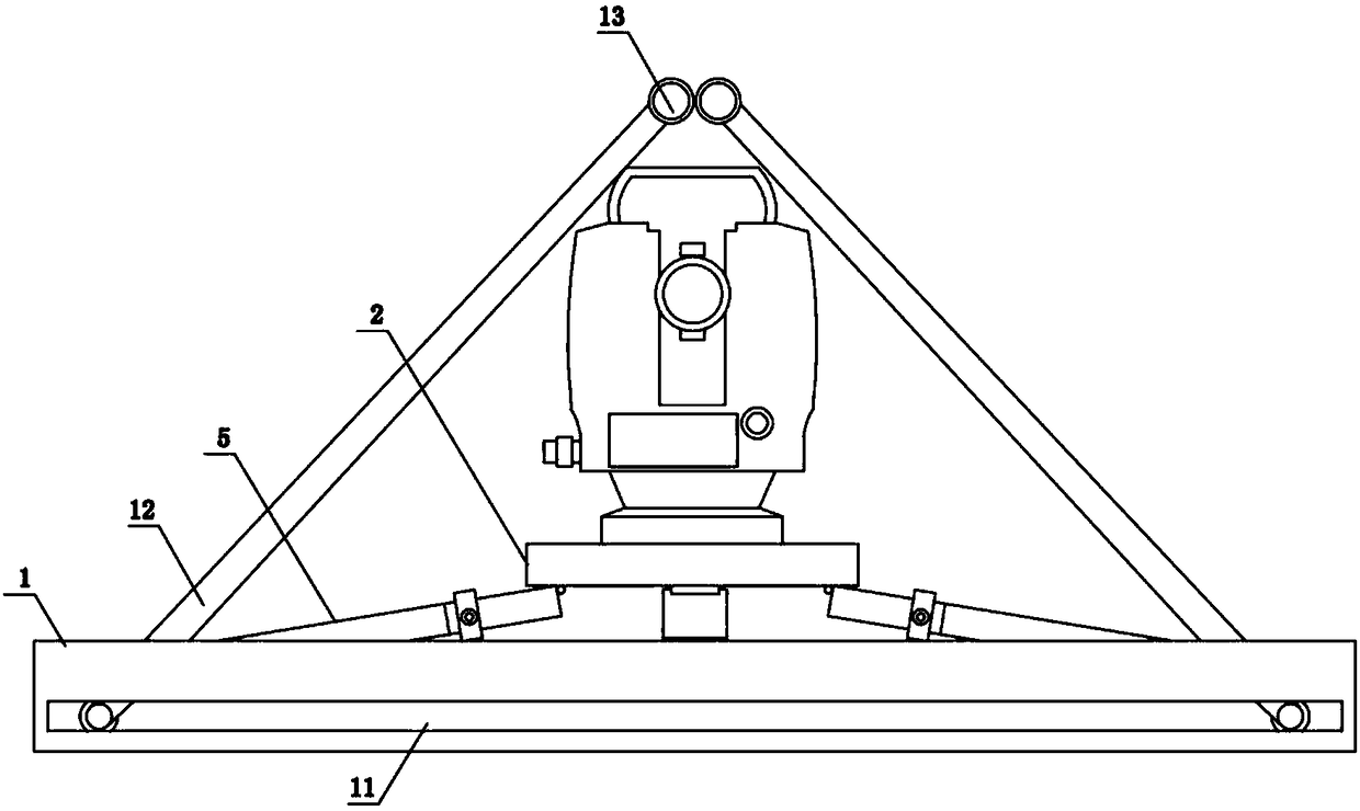
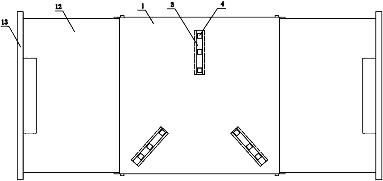
[0035] Such as Figure 1 to Figure 4 Shown, the present invention comprises base plate 1, tripod and support plate 2, base plate 1 is cuboid structure, and three slide grooves 3 are arranged on its upper end surface, and the groove bottom of slide groove 3 is provided with a plurality of blind holes 4, and present embodiment uses three Blind hole is explained, and tripod includes three telescopic rods 5, and telescopic rod 5 adopts a plurality of plugged rod bodies in the prior art, and is positioned by bolt between adjacent rod bodies, and the lower end of telescopic rod 5 is hinged slide rod 6, and slide rod The upper end of 6 is provided with a U-shaped connection part, and the telescopic rod 5 is hinged with the U-shaped connection part through a pin shaft, and the lower end is a columnar structure. A through hole 8 and a chamber 9 are provided. The lower part of the slide bar 6 is provided with a limit boss 10 along the circumferential direction. The limit boss 10 is a co...
Embodiment 2
[0037] The structure of this embodiment is basically the same as that of Embodiment 1, the difference is that: Figure 5 As shown, the lower end surface of the limiting boss 10 is provided with a return spring 14. The return spring 14 is sleeved on the lower end of the slide bar and is located in the chamber 9. The elastic force of the return spring 14 is less than 1 / 3 of the gravity of the supporting device.
Embodiment 3
[0039] The structure of this embodiment is basically the same as that of Embodiment 1, the difference is that: Image 6 As shown, the first magnet 15 on the lower end surface of the support plate 2, the second magnet 16 that is attracted to the first magnet 15 is arranged on the upper end surface of the base plate 1, the upper end surface of the second magnet 16 is fixedly provided with a disc spring assembly 17, and the disc spring The maximum elastic force of the component 17 is smaller than the attraction force between the first magnet 15 and the second magnet 16 .
PUM
 Abstract
Description
Claims
Application Information
 - R&D
- Intellectual Property
- Life Sciences
- Materials
- Tech Scout
- Unparalleled Data Quality
- Higher Quality Content
- 60% Fewer Hallucinations
Browse by: Latest US Patents, China's latest patents, Technical Efficacy Thesaurus, Application Domain, Technology Topic, Popular Technical Reports.
© 2025 PatSnap. All rights reserved.Legal|Privacy policy|Modern Slavery Act Transparency Statement|Sitemap|About US| Contact US: help@patsnap.com


