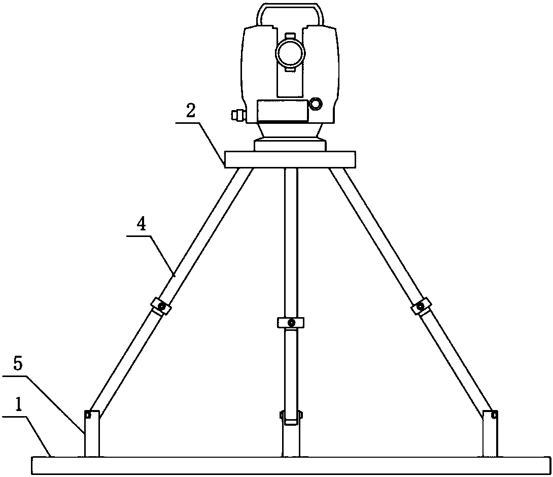
Height adjusting device for surveying and mapping
A technology of height adjustment device and chute, applied in vibration suppression adjustment, spring/shock absorber, supporting machine, etc., can solve the problems of reducing the efficiency of measurement, difficulty in adjustment, complicated adjustment method, etc., to expand the scope and improve the fine-tuning. Amplitude, the effect of increasing the increase
- Summary
- Abstract
- Description
- Claims
- Application Information
AI Technical Summary
Problems solved by technology
Method used
Image
Examples
Embodiment 1
[0031] Such as Figure 1 to Figure 4 As shown, the present invention includes a bottom plate 1, a tripod, and a supporting plate 2. Both the bottom plate 1 and the supporting plate 2 are circular plates. The upper end surface of the bottom plate 1 is provided with a chute 3, and the chute 3 has an arc-shaped structure. The distance D1 from the center of the bottom plate 1 is greater than the distance D2 between the tail end of the chute 3 and the center of the bottom plate 1. The groove depth of the chute 3 decreases from the head end to the end, and the chute 3 is evenly arranged along the circumferential direction. A tripod includes three telescopic rods 4, the telescopic rod 4 adopts multiple plug-in rod bodies in the prior art, and the adjacent rod bodies are positioned by bolts. The lower end of the telescopic rod 4 is hinged with the sliding rod 5, and the lower end of the sliding rod 5 is sleeved. Set the slider 6, the slider 6 is slidingly matched with the sliding groov...
Embodiment 2
[0033] The structure of this embodiment is basically the same as that of the first embodiment, the difference lies in: Figure 5 As shown, the lower end surface of the limiting protrusion 8 is provided with a return spring 10, the return spring 10 is sleeved on the lower end of the slide bar 5 and is located in the chamber 7, and the lower end of the slide bar 5 is provided with a first magnet 11, and the bottom of the blind hole 9 A second magnet 12 attracted to the first magnet 11 is arranged at the end, and the attraction force between the first magnet 11 and the second magnet 12 is greater than the elastic force of the return spring 10.
Embodiment 3
[0035] The structure of this embodiment is basically the same as that of the first embodiment, the difference lies in: Image 6 As shown, the lower end surface of the bottom plate 1 is provided with a groove 13, which can greatly reduce the weight of the entire device, and three sets of shock-absorbing sleeves 14 and walking wheels 15 are arranged on the lower end surface of the bottom plate 1, and the shock-absorbing sleeve 14 is located in the concave On the outside of the groove 13, the structure design can make the entire device slide quickly on a flat road, and the design of the shock-absorbing sleeve 14 can prevent the road bumps from damaging the measuring instrument.
PUM
 Abstract
Description
Claims
Application Information
 - R&D
- Intellectual Property
- Life Sciences
- Materials
- Tech Scout
- Unparalleled Data Quality
- Higher Quality Content
- 60% Fewer Hallucinations
Browse by: Latest US Patents, China's latest patents, Technical Efficacy Thesaurus, Application Domain, Technology Topic, Popular Technical Reports.
© 2025 PatSnap. All rights reserved.Legal|Privacy policy|Modern Slavery Act Transparency Statement|Sitemap|About US| Contact US: help@patsnap.com


