
High-penetration microstructure optical film possessing partial light condensed function

An optical film and microstructure technology, applied in optics, condenser mirrors, optical components, etc., can solve problems such as insufficient practicability, and achieve the effect of avoiding reflection

Pending Publication Date: 2018-08-31
四川省维奇光电科技有限公司
View PDF0 Cites 0 Cited by
  • Summary
  • Abstract
  • Description
  • Claims
  • Application Information

AI Technical Summary

Problems solved by technology

[0002] When the light passes through the transparent substrate, the incident light will be affected by the refractive index of the transparent substrate, and some of the light will be reflected. Therefore, general displays, optoelectronic devices, optical communication devices, solar cells and lighting system devices are Reduce its light reflectivity, more than the light-transmitting substrate is equipped with a sub-wavelength microstructure like a moth eye structure, so that the refractive index of the transparent substrate surface changes gradually along the depth direction, so as to avoid light due to the refractive index Reflection phenomenon caused by sharp changes, which mainly includes a base and a plurality of structures, the elastic modulus of the structure is above 1MPa and below 1200MPa, and the above-mentioned structure system is arranged on the surface of the base, and the above-mentioned structure material and contains protrusions or recesses, and the aspect ratio of the aforementioned protrusions or recesses is not less than 0.6 and not more than 1.5. However, although the aforementioned structures can achieve the purpose of reducing light reflection by means of sub-wavelength microstructures, they cannot effectively gather Light source, so the practicability is less

Method used


Image

  • High-penetration microstructure optical film possessing partial light condensed function
  • High-penetration microstructure optical film possessing partial light condensed function
  • High-penetration microstructure optical film possessing partial light condensed function

Examples


Embodiment Construction

[0016] The following will clearly and completely describe the technical solutions in the embodiments of the present invention with reference to the accompanying drawings in the embodiments of the present invention. Obviously, the described embodiments are only some, not all, embodiments of the present invention. Based on the embodiments of the present invention, all other embodiments obtained by persons of ordinary skill in the art without making creative efforts belong to the protection scope of the present invention.

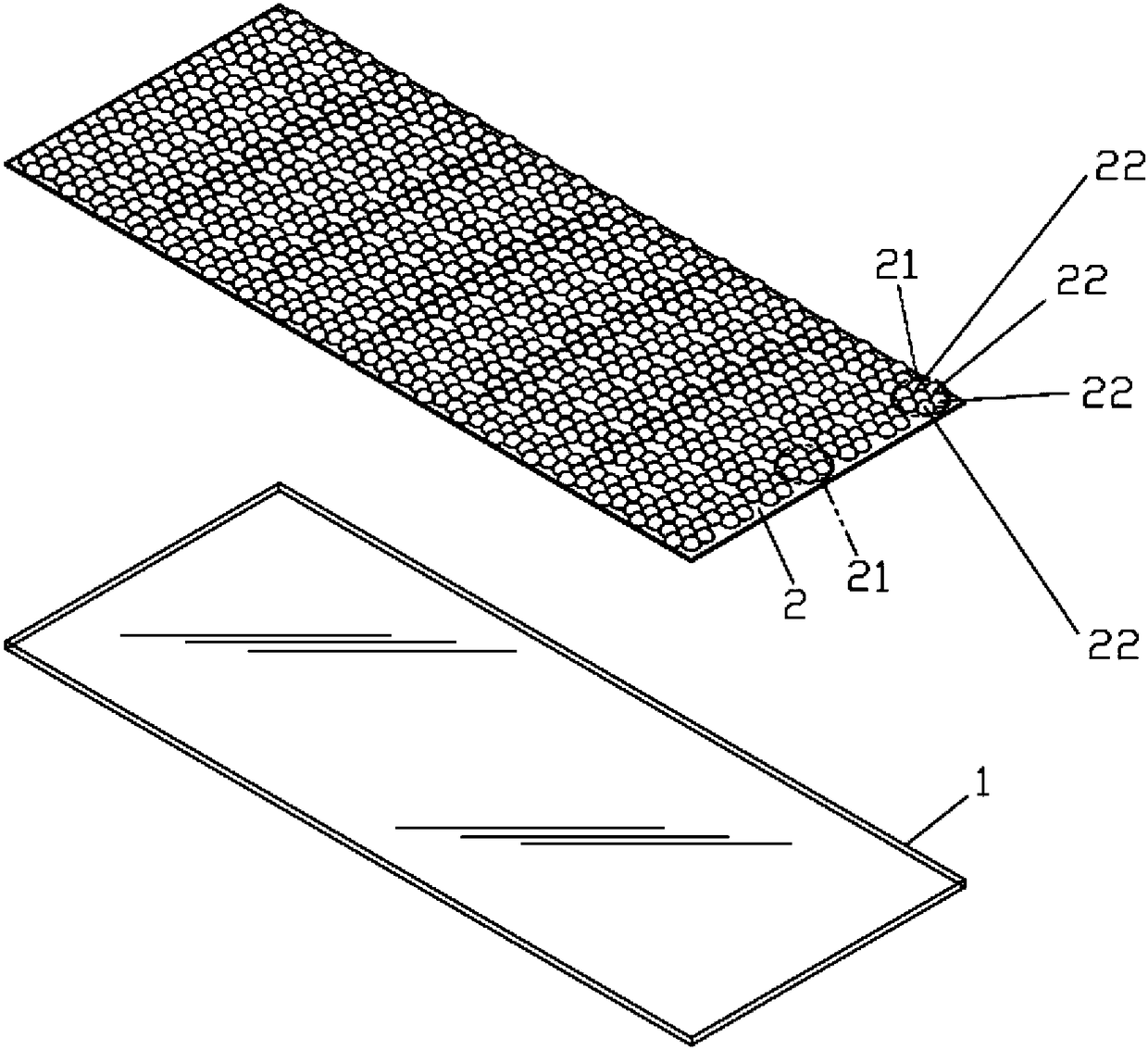
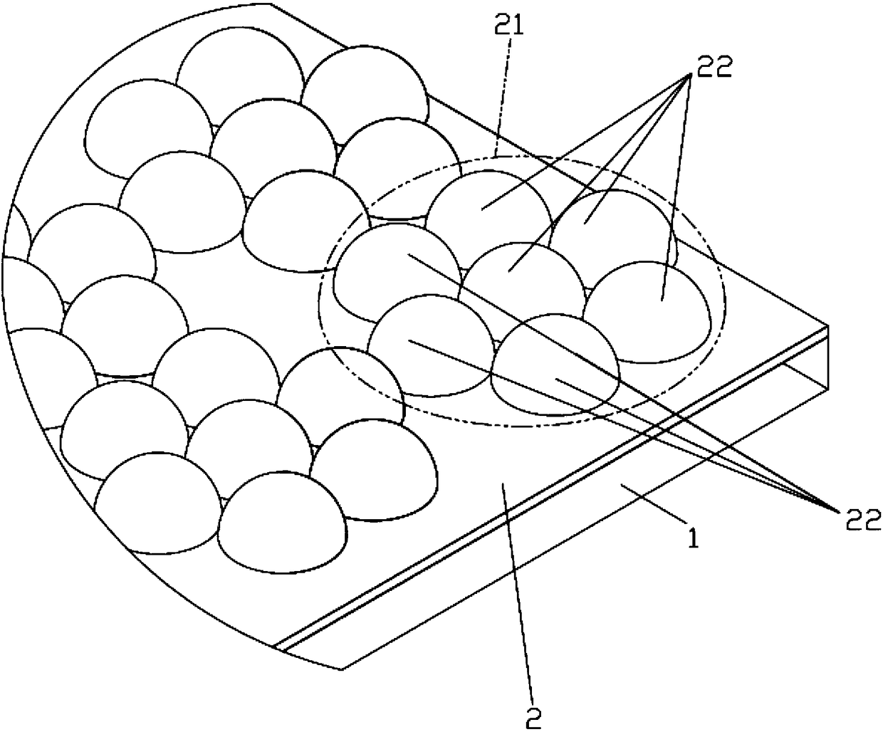
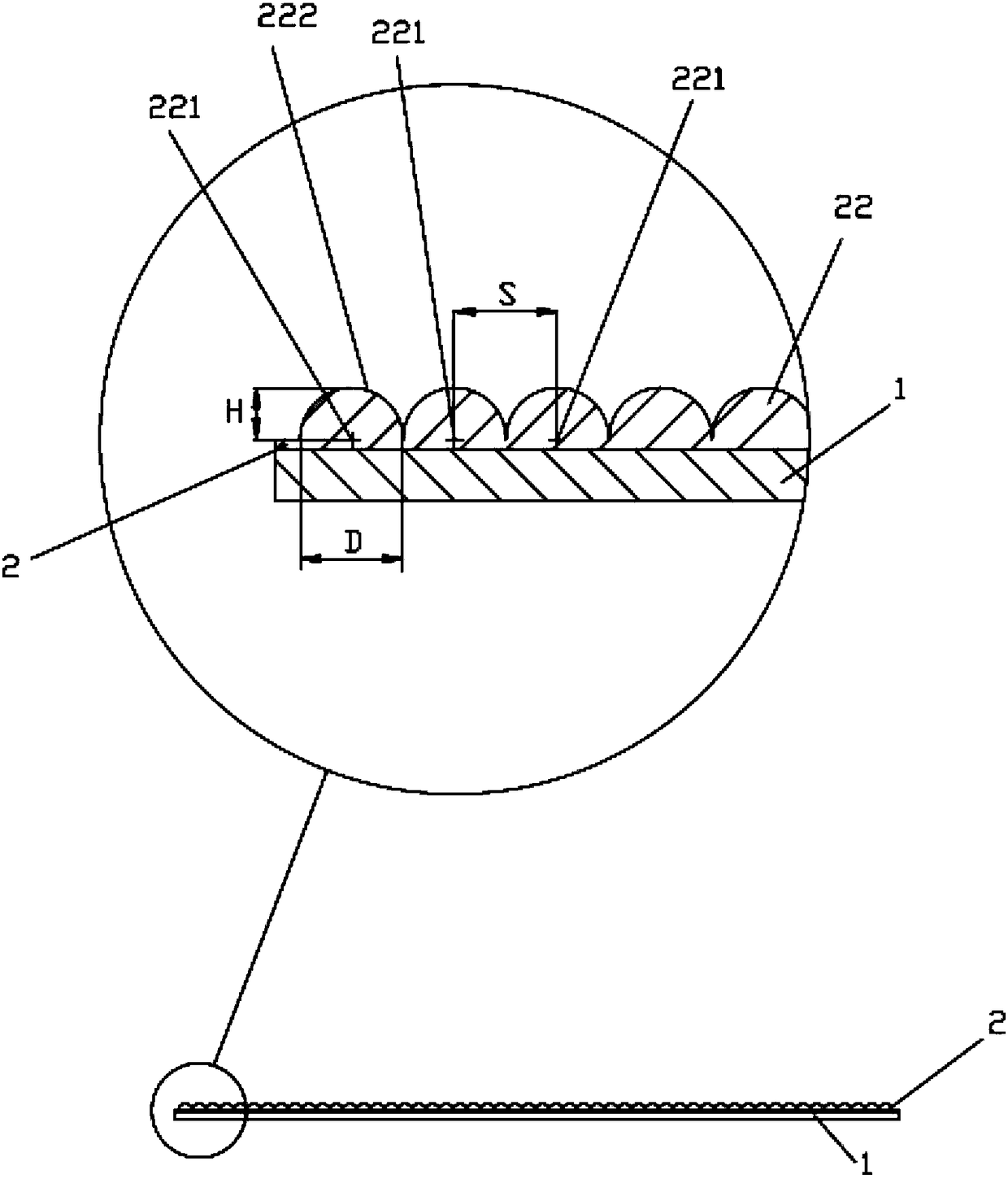
[0017] Such as Figure 1-Figure 4 Shown: a microstructured optical film with high penetration and polarized light concentrating function, including a transparent substrate 1, and the transparent polymer plate can be made of polymethylmethacrylate (PMMA), polycarbonate (Polycarbonate) or Polyester; anti-reflection light-transmitting layer 2, the anti-reflection light-transmitting layer 2 is set on the transparent substrate 1, and the anti-reflection light-trans...


PUM


Abstract

A high-penetration microstructure optical film possessing a partial light condensed function comprises a transparent substrate and an antireflective light transmission layer. The antireflective lighttransmission layer is arranged on the transparent substrate. The antireflective light transmission layer is at least provided with a light condensed area. The light condensed area is provided with seven subwavelength microstructures. The six subwavelength microstructures surround one subwavelength microstructure. Each subwavelength microstructure is in a semicircle ball shape and possesses the center of a circle and one circumferential surface. The vertical distance between the center of the circle and the circumferential surface of each subwavelength microstructure is a height H. The maximumdistance of the two sides of the circumferential surface is a diameter D. The distance of the centers of the circle of the adjacent subwavelength microstructures is a spacing S. The height H, the diameter D and the spacing S are between 0.03 micrometers to 0.4 micrometers. In the invention, through a subwavelength microstructure shape and an equidistant annular arrangement design, antireflection and light source gathering functions are achieved.

Description

technical field [0001] The invention relates to an optical thin film, in particular to a microstructure optical thin film with high penetration and polarized light concentration function. Background technique [0002] When the light passes through the transparent substrate, the incident light will be affected by the refractive index of the transparent substrate, and some of the light will be reflected. Therefore, general displays, optoelectronic devices, optical communication devices, solar cells and lighting system devices are Reduce its light reflectivity, more than the light-transmitting substrate is equipped with a sub-wavelength microstructure like a moth eye structure, so that the refractive index of the transparent substrate surface changes gradually along the depth direction to avoid light due to the refractive index Reflection phenomenon caused by sharp changes, which mainly includes a base and a plurality of structures, the elastic modulus of the structure is above...

Claims


Application Information

Patent Timeline
IPC IPC(8): G02B1/11G02B1/118G02B19/00
CPCG02B19/0009G02B1/11G02B1/118
Inventor 李明伟
Owner 四川省维奇光电科技有限公司
Learn More