
Plasma display screen

A plasma display and display electrode technology, applied in the direction of optical/shielding devices, gas discharge tubes/containers, electrical components, etc., can solve the problems of not being used, achieve the effect of preventing reflection and improving the contrast of the screen

Inactive Publication Date: 2007-06-06
SAMSUNG SDI CO LTD
View PDF2 Cites 0 Cited by
  • Summary
  • Abstract
  • Description
  • Claims
  • Application Information

AI Technical Summary

Problems solved by technology

[0017] However, in the method described above using grayscale compensation, not all of the 255 sustain pulses required for the highest green and red brightness are used

Method used


Image

  • Plasma display screen
  • Plasma display screen
  • Plasma display screen

Examples


Embodiment Construction

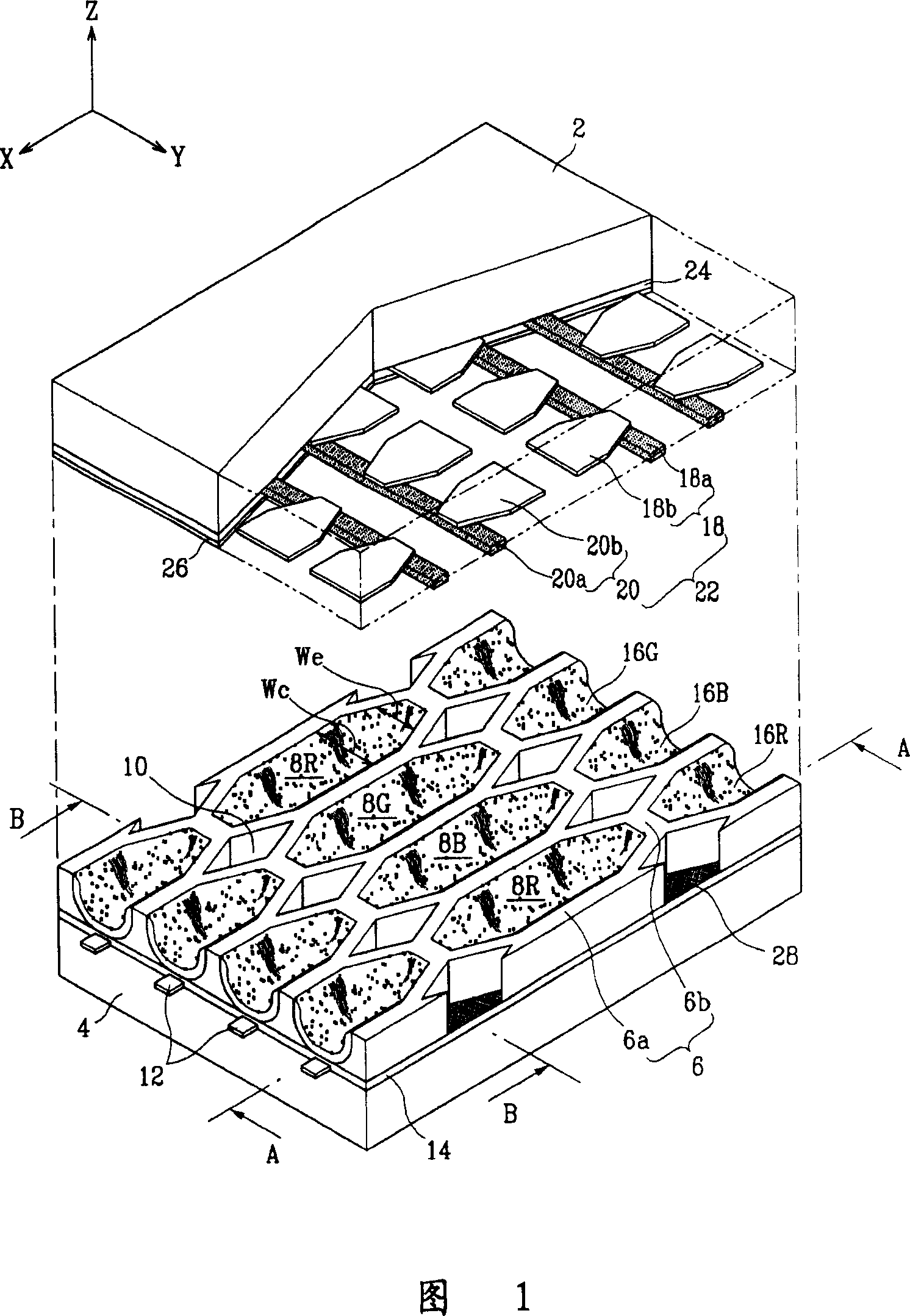
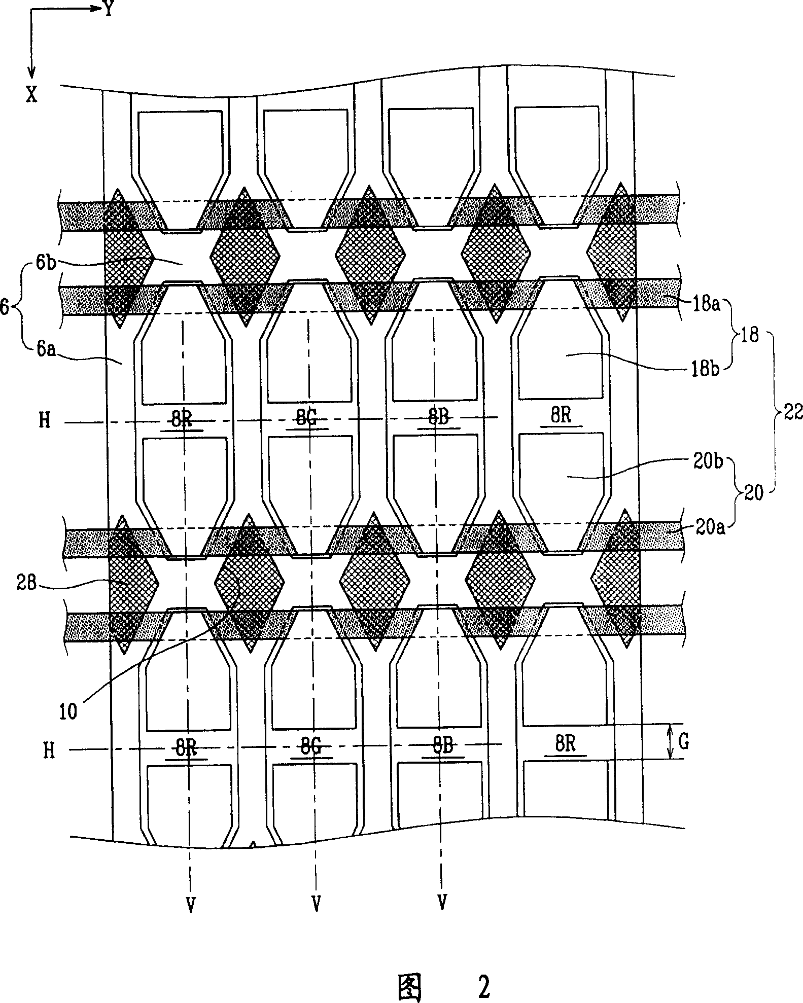
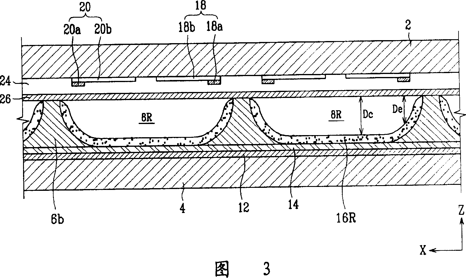
[0066] FIG. 1 is a partially exploded perspective view of a plasma display panel according to a first embodiment of the present invention. FIG. 2 is a partial top view of the plasma display screen in FIG. 1 . Fig. 3 is a sectional view along the line A-A in Fig. 1 .

[0067] A plasma display panel (PDP) according to the first embodiment includes a first substrate 2 and a second substrate 4 arranged substantially parallel at a predetermined interval. Non-discharge region 10 and discharge cells 8R, 8G, 8B are defined by partition wall 6 between first substrate 2 and second substrate 4 .

[0068] A plurality of address electrodes 12 are formed along one direction (X direction in the figure) on the surface of the second substrate 4 opposite to the first substrate 2 . As an example, the address electrodes 12 are formed in a stripe pattern with the same predetermined interval between adjacent address electrodes 12 . A dielectric layer 14 covering the address electrodes 12 is form...


PUM


Abstract

A plasma display panel. A first substrate and a second substrate are provided opposing one another with a predetermined gap therebetween. Address electrodes are formed on the second substrate. Barrier ribs are mounted between the first substrate and the second substrate, the barrier ribs defining a plurality of discharge cells and a plurality of non-discharge regions. Phosphor layers are formed within each of the discharge cells. Discharge sustain electrodes are formed on the first substrate. The non-discharge regions are formed in areas encompassed by discharge cell abscissas and ordinates that pass through centers of each of the discharge cells. Also, external light absorbing members are formed at areas of the external surface of the first substrate corresponding to locations of the non-discharge regions.

Description

[0001] This application is a divisional application of the patent application with the filing date of June 25, 2004, the application number of 200410061813.8, and the invention name of "plasma display screen". [0002] Cross-Referenced Related Applications [0003] This application claims priority and benefits from the following patent applications filed with the Korean Patent Office: No. 2003-0041491 filed on June 25, 2003, No. 2003-0044861 filed on July 3, 2003, No. 2003-0050278 filed on 22nd, No. 2003-0052598 filed on July 30, 2003, No. 2003-0053461 filed on August 1, 2003, No. 2003- filed on October 21, 2003 0073518 and No. 2003-0073519 filed October 21, 2003, the contents of which are incorporated herein by reference. technical field [0004] The present invention relates to a plasma display screen (PDP), and more particularly, to a plasma display screen having a structure for preventing reflection of external light to improve screen contrast. Background technique [...

Claims


Application Information

Patent Timeline
IPC IPC(8): H01J17/49H01J17/02H01J17/04H01J11/00H01J11/02H01J11/36H01J11/22
CPCH01J11/24H01J11/28H01J11/44H01J2211/444
Inventor 禹锡均金禹泰权泰正许银起权宰翊姜景斗柳宪锡
Owner SAMSUNG SDI CO LTD
Learn More