Corrugated steel outside lining concrete structure for underground utility tunnel
A technology of concrete structure and comprehensive pipe gallery, which is applied to underwater structures, infrastructure engineering, water conservancy projects, etc., can solve the problem of insufficient stable bearing capacity of corrugated steel pipe gallery structure, easy fracture of prefabricated pipe gallery joints, and uneven foundation resistance. Settlement and other problems, to achieve the effect of improving the performance of anti-uniform settlement of the foundation, excellent leakage prevention effect, and improving the convenience of connection
- Summary
- Abstract
- Description
- Claims
- Application Information
AI Technical Summary
Problems solved by technology
Method used
Image
Examples
specific Embodiment approach 1
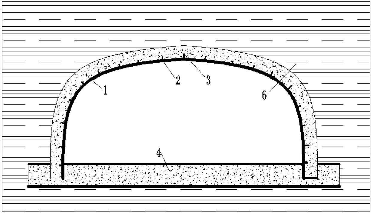
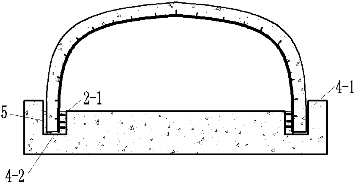
[0021] Specific Embodiment 1: The corrugated steel-lined concrete structure used in the underground comprehensive pipe gallery in this embodiment includes an outer-lined reinforced concrete ring 1, an arch body corrugated steel plate 2 and a bottom plate 4, wherein the outer-lined concrete ring 1 is wrapped on the arch body corrugated An arch body is formed on the outer surface of the steel plate 2, and cup grooves 4-2 are respectively opened on the left and right sides of the bottom plate 4 in the horizontal direction, and pegs 2-1 are arranged at the arch feet of the corrugated steel plate 2 of the arch body, and the arch body The arch foot is inserted into the cup mouth groove 4-2, and the arch foot concrete 5 is poured in the cup mouth groove 4-2, and the surrounding soil 6 is wrapped around the arch body and the bottom plate 4 to form an underground comprehensive pipe gallery. Corrugated steel-lined concrete structure.
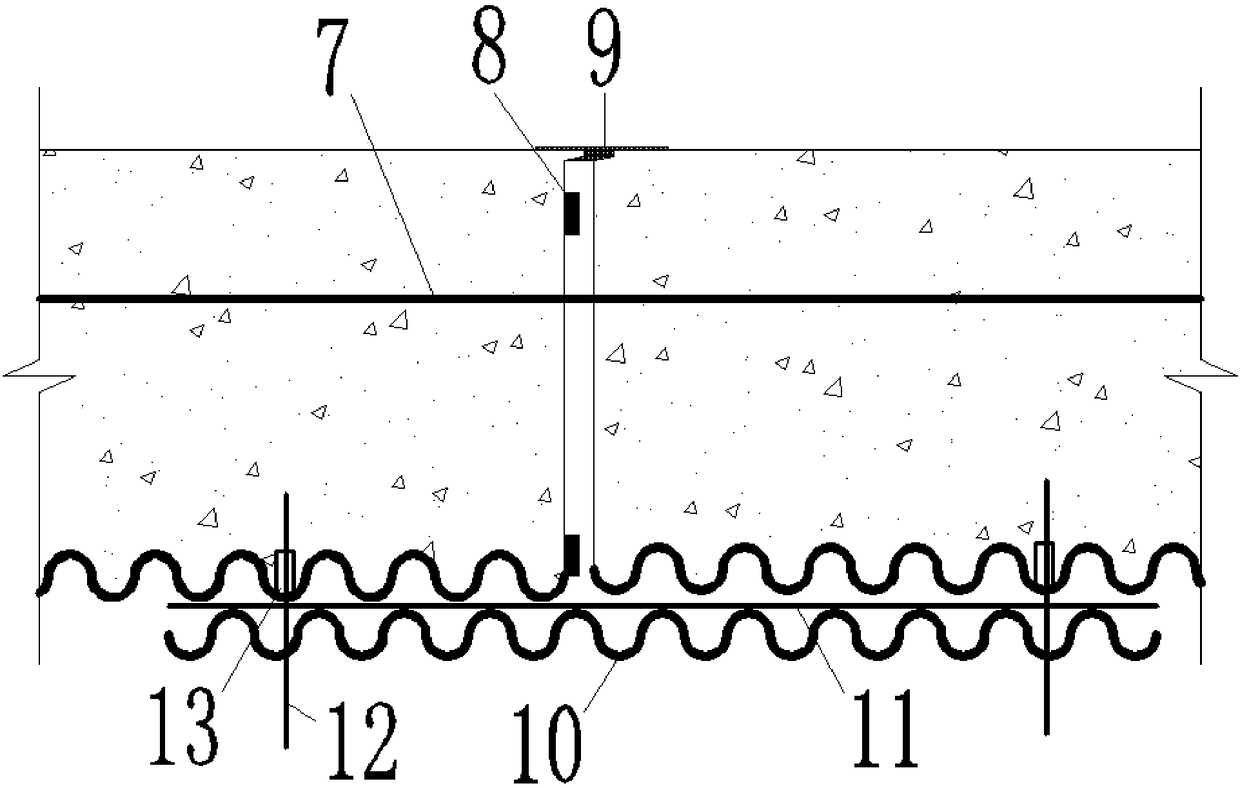
[0022] The prefabricated segmental connection of th...
specific Embodiment approach 2
[0024] Embodiment 2: This embodiment differs from Embodiment 1 in that flanges 4-1 are provided on the left and right lateral sides of the bottom plate 4, and the arch body is located between the flanges 4-1 on the left and right sides.
[0025] The structural schematic diagram of the flange of this embodiment is as follows figure 2 shown.
specific Embodiment approach 3
[0026] Embodiment 3: This embodiment differs from Embodiment 1 or Embodiment 2 in that the base plate 4 is a reinforced concrete base plate.
PUM
 Abstract
Description
Claims
Application Information
 - R&D
- Intellectual Property
- Life Sciences
- Materials
- Tech Scout
- Unparalleled Data Quality
- Higher Quality Content
- 60% Fewer Hallucinations
Browse by: Latest US Patents, China's latest patents, Technical Efficacy Thesaurus, Application Domain, Technology Topic, Popular Technical Reports.
© 2025 PatSnap. All rights reserved.Legal|Privacy policy|Modern Slavery Act Transparency Statement|Sitemap|About US| Contact US: help@patsnap.com


