
A resource-saving industrial waste gas heat energy secondary utilization device

An industrial waste gas and resource saving technology, applied in waste heat treatment, energy-saving heating/cooling, water heater and other directions, can solve the problems of low boiler heat utilization rate, serious energy consumption, low flue gas utilization rate, etc., to save energy, The effect of improving heat utilization and reducing energy consumption

Inactive Publication Date: 2019-06-07
广东净尘环保设备有限公司
View PDF4 Cites 0 Cited by
  • Summary
  • Abstract
  • Description
  • Claims
  • Application Information

AI Technical Summary

Problems solved by technology

[0005] At present, in the use of boilers in industrial production in my country, the heat utilization rate of boilers is low, and flue gas is the main way of energy consumption of industrial equipment. The main energy consumption of machines, dryers and kilns is exhausted through flue gas, while the existing industrial waste gas recovery device usually consists of a smoke collecting box, a flue gas inlet and outlet on the smoke collecting box, a heated medium inlet and outlet, And heat exchange tubes, due to structural defects, the flue gas utilization rate of the existing industrial waste gas recovery device is low, and the energy consumption is still very serious, which is in contradiction with the increasingly severe energy shortage problem at the present stage, and it is difficult to meet the production demand at the present stage

Method used


Image

  • A resource-saving industrial waste gas heat energy secondary utilization device
  • A resource-saving industrial waste gas heat energy secondary utilization device
  • A resource-saving industrial waste gas heat energy secondary utilization device

Examples


Embodiment Construction

[0021] It should be noted that, in the case of no conflict, the embodiments of the present invention and the features in the embodiments can be combined with each other.

[0022] In describing the present invention, it should be understood that the terms "center", "longitudinal", "transverse", "upper", "lower", "front", "rear", "left", "right", " The orientations or positional relationships indicated by "vertical", "horizontal", "top", "bottom", "inner" and "outer" are based on the orientations or positional relationships shown in the drawings, and are only for the convenience of describing the present invention and Simplified descriptions, rather than indicating or implying that the device or element referred to must have a particular orientation, be constructed and operate in a particular orientation, and thus should not be construed as limiting the invention. In addition, the terms "first", "second", etc. are used for descriptive purposes only, and should not be understood ...


PUM


Abstract

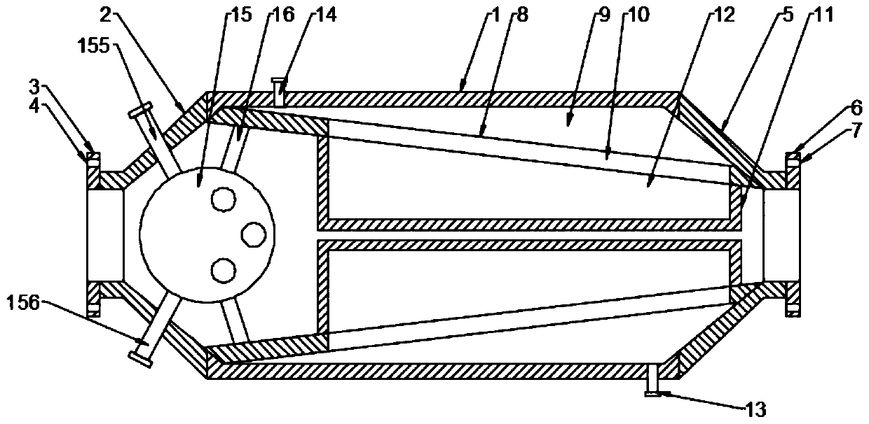
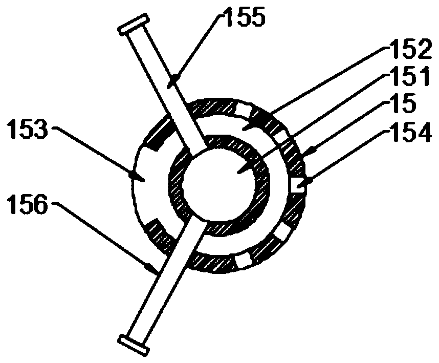
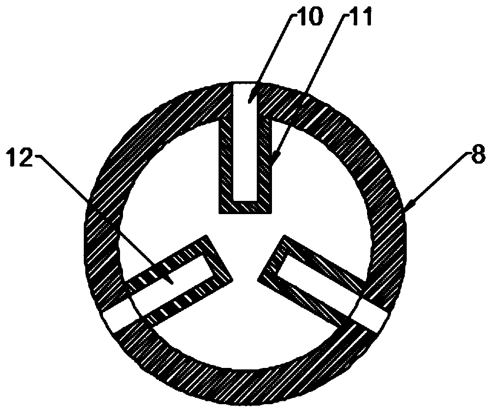
The invention discloses a resource-saving industrial waste gas heat energy secondary utilization device. The device comprises a cylinder; the left side end of the cylinder communicates with an intakepipe; the right side end of the cylinder communicates with an exhaust pipe; a heat exchange cylinder is arranged in an inner cavity of the cylinder; the heat exchange cylinder and the inner wall of the cylinder form a first water cavity; multiple groove holes are uniformly formed in the inner side wall of the first water cavity; heat exchange fins sleeve openings on the inner sides of the groove holes; and a heat exchange ball is arranged on the side, near the intake pipe, of the inner cavity of the cylinder. High-temperature industrial waste gas enters a second heat exchange cavity from an intake hole for heat exchange with water in a second water cavity; heat in high-temperature industrial waste gas is absorbed at the first time; the heat-absorbed industrial waste gas directly enters theheat exchange cylinder for heat exchange with the water through the heat exchange fins; and the secondary heat exchange reaction is performed for further absorbing the heat in the industrial waste gas, so that the heat in the industrial waste gas is fully reutilized, the heat utilization rate is increased, the energy consumption is reduced, and the energy is greatly saved.

Description

technical field [0001] The invention relates to the field of energy-saving equipment, in particular to a resource-saving industrial waste gas heat energy secondary utilization device. Background technique [0002] The boiler is a kind of energy conversion equipment. The energy input to the boiler includes chemical energy and electric energy in the fuel, and the boiler outputs steam, high-temperature water or organic heat carrier with a certain amount of heat energy. [0003] The original meaning of the pot refers to the water container heated on the fire, and the furnace refers to the place where fuel is burned. The boiler includes two parts: the pot and the furnace. The hot water or steam generated in the boiler can directly provide the required heat energy for industrial production and people's life, and can also be converted into mechanical energy through a steam power device, or converted into electrical energy through a generator. Boilers that provide hot water are cal...

Claims


Application Information

Patent Timeline
Patent Type & Authority Patents(China)
IPC IPC(8): F28D7/00F28D21/00F27D17/00F24H1/00
CPCF24H1/00F27D17/004Y02B30/56Y02P10/25
Inventor 张俊定
Owner 广东净尘环保设备有限公司
Learn More