
Injection molding method for plate grids

A grid and mold cavity technology, which is applied in the field of battery processing, can solve problems such as poor fluidity, high surface tension of mixed materials, and unclear edges and corners of the grid.

Inactive Publication Date: 2018-08-28
GUANGZHOU ZHUOYUE POWER NEW ENERGY CO LTD
View PDF7 Cites 1 Cited by
  • Summary
  • Abstract
  • Description
  • Claims
  • Application Information

AI Technical Summary

Problems solved by technology

The carbon fiber composite grid is processed by injection molding. Since the carbon fiber composite grid uses a variety of fibers as raw materials, various fibers need to be mixed and melted into a mixed material during injection molding. Since the mixed material is in the form of a colloid, its fluidity is poor , and the surface tension of the mixed material is also high, so the mixed material is not easy to enter some narrow grooves in the mold cavity; and the carbon fiber composite grid needs sharper edges and corners, so the grids processed according to the current injection molding method have no angles. clear

Method used


Image

  • Injection molding method for plate grids
  • Injection molding method for plate grids

Examples


Embodiment Construction

[0031] The present invention will be described in further detail below by means of specific embodiments:

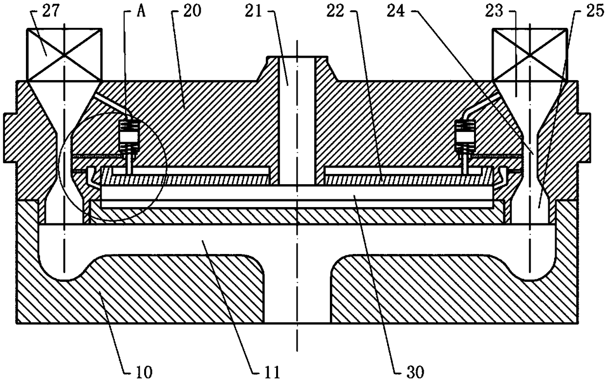
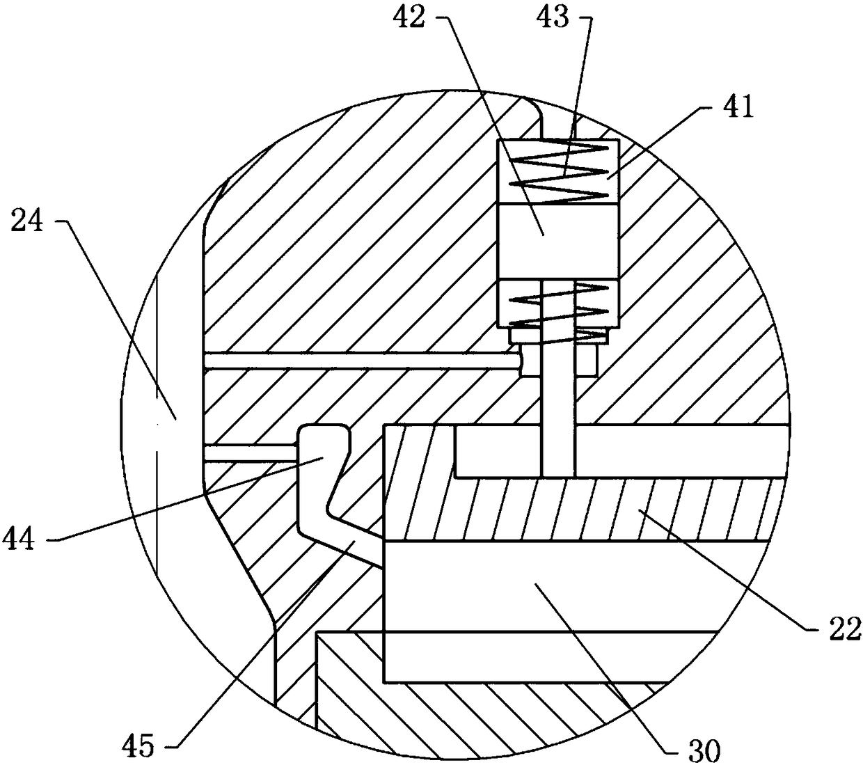
[0032] The reference signs in the drawings of the description include: lower mold 10, water flow cooling channel 11, upper mold 20, injection port 21, template 22, inlet section 23, throat 24, diffusion section 25, two-position two-way electromagnetic reversing valve 27. Die cavity 30, pressure chamber 41, piston 42, balance spring 43, residual material chamber 44, wedge mouth 45.

[0033] The injection molding method of the grid in this embodiment uses an injection molding device to inject the grid. like figure 1 , figure 2 As shown, the injection molding equipment includes an injection molding machine, an upper mold 20 and a lower mold 10, and the upper mold 20 and the lower mold 10 are fixed to each other by bolts, so that the upper mold 20 and the lower mold 10 are detachable. The upper mold 20 is provided with an air flow cooling passage, and the lower mold 10 is...


PUM


Abstract

The invention relates to the technical field of battery processing, and particularly discloses an injection molding method for plate grids. The method comprises the following steps that 1, the side wall of a die cavity is cleaned, and an upper die and a lower die are combined to form the complete die cavity; 2, a pump body and the entrance section are disconnected, and a water flow cooling channeland a vacuum pump are connected; 3, materials are injected into the die cavity, and meanwhile a jet channel is vacuumized; 4, the pump body and the entrance section are connected, cooling water is introduced into the water flow cooling channel continuously till a plate grid inside the die cavity is cooled and molded, the pump body is turned off, and water injection into the water flow cooling channel is stopped; 5, the upper die and the lower die are disassembled, and the mold plate grid is taken out from the die cavity. According to the injection molding method, when materials are injected into the die cavity, the space of the die cavity is larger than the space, formed when cooling water is injected, of the die cavity, the purpose that materials are extruded when the die cavity is decreased after materials are injected into the die cavity, and materials can enter the small interval so that the molded plate grid can have the clear corner angles.

Description

technical field [0001] The invention relates to the technical field of battery processing, in particular to an injection molding method of a grid. Background technique [0002] At present, lead-acid batteries used in large quantities on the market use lead as the grid and sulfuric acid as the electrolyte. The use of lead-acid batteries has a history of 150 years. Although lead-acid batteries have the disadvantages of large pollution, large volume, heavy weight, and slow charging; but for other types of batteries, they also have the advantages of low cost, safety, and large capacity. Therefore, lead-acid batteries are still widely used in various industries. [0003] Aiming at the defects of lead-acid batteries, colloidal lead-acid batteries were invented abroad. It is made of fumed silicon dioxide and added with additives to make a colloidal electrolyte to replace the pure sulfuric acid electrolyte. The colloidal battery improves the battery charging and discharging capac...

Claims


Application Information

Patent Timeline
IPC IPC(8): B29C45/00B29C45/26B29C45/34B29C45/73H01M4/73B29K23/00B29K79/00
CPCB29C45/0001B29C45/26B29C45/34B29C45/7207B29C45/73B29K2023/12B29K2079/00H01M4/73Y02E60/10
Inventor 何幸华李政文黎少伟何可立马俊
Owner GUANGZHOU ZHUOYUE POWER NEW ENERGY CO LTD
Learn More