Compact antigravity loop heat pipe

A loop heat pipe, anti-gravity technology, used in indirect heat exchangers, lighting and heating equipment, etc., can solve the problems of large system space, unreliable work, complicated structure, etc., to save system space, reduce system space, and structure simple effect

Pending Publication Date: 2018-08-21
TECHNICAL INST OF PHYSICS & CHEMISTRY - CHINESE ACAD OF SCI
View PDF6 Cites 0 Cited by
  • Summary
  • Abstract
  • Description
  • Claims
  • Application Information

AI Technical Summary

Problems solved by technology

[0006] The purpose of the present invention is to provide a compact anti-gravity loop heat pipe, which is used to solve or partly solve the problem that there are usually two, three or even more transmission pipelines between the evaporator and the condenser of the existing loop heat pipe, and the structure is complicated. Occupies a larger system space; and many loop heat pipes need the assistance of gravity to operate normally, and the problem of unreliable work in a horizontal state or an anti-gravity state

Method used


Image

  • Compact antigravity loop heat pipe
  • Compact antigravity loop heat pipe
  • Compact antigravity loop heat pipe

Examples


Embodiment 1

[0087] This embodiment has the same basic structure as the above-mentioned embodiments. For the sake of brevity, in the description process of this embodiment, the same technical features as the above-mentioned embodiments will not be described in detail to illustrate that this embodiment is different from the above-mentioned embodiments. Mainly:

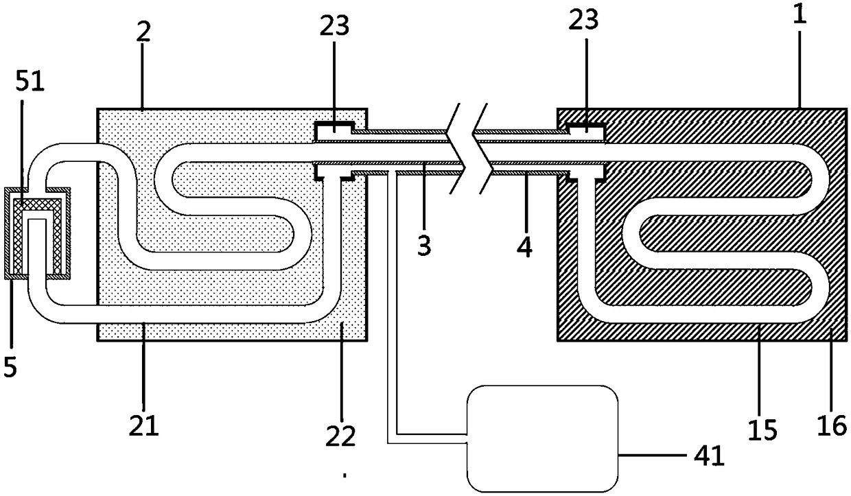
[0088] refer to figure 2 , This embodiment provides a compact anti-gravity loop heat pipe On the basis of the above embodiments, the evaporator 1 is a cylindrical structure. A liquid-absorbing core 11 is arranged in the evaporator 1 , and the liquid-absorbing core 11 is cup-shaped with an open side close to the liquid pipeline and a closed side away from the liquid pipeline. That is, the liquid-absorbing core 11 is a cylindrical shape with an opening at one end, and the opening end faces the liquid pipeline.

[0089] A baffle 14 is provided at the end of the opening side of the liquid-absorbing core 11 to isolate the inner space ...


PUM


Abstract

The invention relates to the technical field of thermal control equipment, and discloses a compact antigravity loop heat pipe, wherein a liquid pipeline, an evaporator, a gas pipeline and a condenserare sequentially connected to form a loop, and the loop heat pipe further comprises a secondary evaporator; the liquid pipeline and the gas pipeline are of a pipe-in-pipe structure, and the secondaryevaporator is communicated with a condenser pipe of the condenser. According to the compact antigravity loop heat pipe disclosed by the invention, by setting the gas pipeline and the liquid pipeline into the pipe-in-pipe structure, only small pipe space is required between the evaporator and the condenser, the structure is simple, the space occupied by a system is reduced, and the flexible layoutof the system is facilitated; in a low temperature environment, the thermal insulation protection can be more conveniently performed on the outside of the pipeline, thereby greatly saving the system space; by setting the secondary evaporator, auxiliary power is provided for the circulating flow of a working medium in the pipeline, so that the loop heat pipe can be reliably started and operated when the loop heat pipe is in a horizontal state or in an antigravity state.

Description

technical field [0001] The invention relates to the technical field of thermal control equipment, in particular to a compact anti-gravity loop heat pipe. Background technique [0002] A heat pipe is a highly efficient heat transfer device, its heat transfer capacity is one or two orders of magnitude higher than that of metal, and it is called a thermal superconductor. The traditional heat pipe mainly includes a metal shell, capillary structure and working medium. The capillary structure is usually composed of channels or sintered porous structures, and is distributed along the entire length of the heat pipe. Although the structure is simple, the flexibility is poor. With a full capillary structure, the liquid flow resistance is relatively large, and the liquid and gas flow in opposite directions in the same space, and there is a problem of carrying, which affects the further improvement of the heat transfer capacity of the heat pipe. [0003] The loop heat pipe is also a th...

Claims


Application Information

Patent Timeline
Patent Type & Authority Applications(China)
IPC IPC(8): F28D15/02F28D15/04
CPCF28D15/0266F28D15/043
Inventor 赵雅楠陈厚磊梁惊涛
Owner TECHNICAL INST OF PHYSICS & CHEMISTRY - CHINESE ACAD OF SCI
Why Eureka
Try Eureka