


Quick Research
Generate reliable direction feasibility study reports for your R&D in just a few steps.

Technical Q&A
Discover and master advanced knowledge NOW. Basics, ideas, possibilities, all at once.

Find Solutions
As an expert in R&D theories, this can generate solutions to your technical problems instantly.

Evaluate Feasibility
Analyze your overall solution with one click, know your potential R&D risks in advance.

Monitor Landscape
Get weekly tech updates, stay abreast of the latest tech innovations and key insights.
Aluminum cell cathode structure capable of reducing horizontal current and improving current distribution
A current distribution and aluminum electrolytic cell technology, applied in the field of aluminum electrolysis, can solve the problems of low current density of aluminum liquid, unstable aluminum liquid, low current efficiency, etc., and achieve reduced energy consumption of aluminum electrolysis, small electromagnetic force, and lower cell voltage Effect
- Summary
- Abstract
- Description
- Claims
- Application Information
AI Technical Summary
Problems solved by technology
Method used
Image


Examples
Embodiment 1
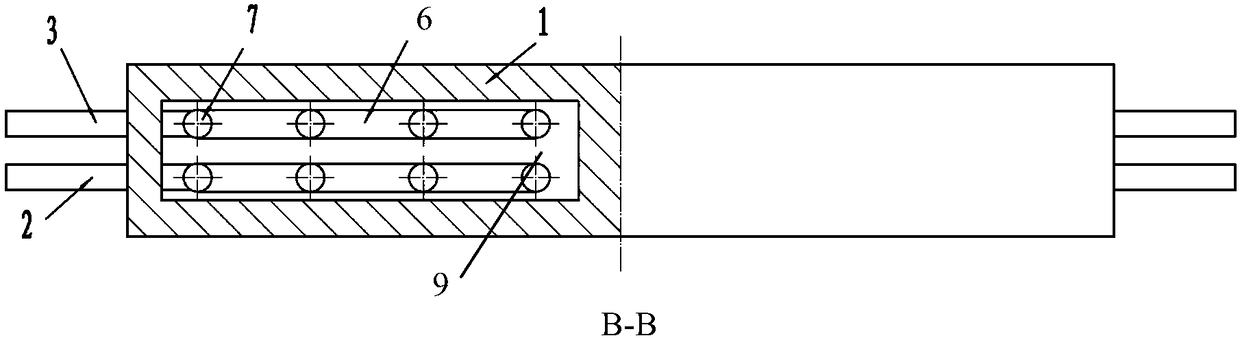
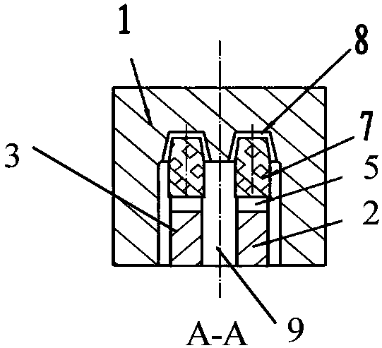
[0043] The cathode structure of the aluminum electrolytic cell that reduces the horizontal current and improves the current distribution such as figure 1 As shown, the B-B direction structure is as follows figure 2 As shown, the A-A direction structure is as follows image 3 as shown, image 3 The cross-sectional structure of the middle cathode carbon block is as follows: Figure 4 As shown, it includes a cathode carbon block (1) and a cathode conductive rod. The shape of the cathode carbon block is a cuboid, and the bottom surface is provided with a cathode groove along the axial direction. The cathode groove is composed of two coaxial and symmetrical long grooves (9). The top surface of the top is provided with 16 grooves (10); two pairs of cathode conductive rods are respectively located in two long grooves (9);
[0044] Each pair of cathode conductive rods is composed of cathode conductive rod I (2) and cathode conductive rod II (3);
[0045] Each cathode conductive r...
Embodiment 2
[0058] The cathode structure of the aluminum electrolytic cell that reduces the horizontal current and improves the current distribution such as Figure 5 As shown, the B-B direction structure is as follows Figure 6 As shown, the A-A direction structure is as follows Figure 7 Shown, structure is the same as embodiment 1, difference is:
[0059] (1) The cathode groove is a through groove (14), and the top surface of the cathode groove is provided with 6 grooves; two cathode conductive rods are symmetrically arranged in a through groove; each conductive claw is equipped with 3 claw heads ( 11); the claw heads on each cathode conductive rod are arranged in a row along the axial direction of the cathode carbon block;
[0060] (2) Each claw head (11) of each cathode conductive rod is connected with the main rod (5) through the support rod (7), and the connection part between the main rod (5) and the support rod (7) and the two is the horizontal The rods (6) jointly constitute ...
Embodiment 3
[0067] The cathode structure of the aluminum electrolytic cell that reduces the horizontal current and improves the current distribution is the same as that of Example 1, the difference is that:
[0068] (1) The cathode groove is a through groove; two cathode conductive rods are symmetrically arranged in a through groove; each conductive claw is equipped with 8 claw heads (11); the claw heads (11) on each cathode conductive rod Arranged in 2 rows along the axis of the cathode carbon block;
[0069] (2) Each claw head (11) of each cathode conductive rod is connected with the main rod (5) through a strut (7), and the strut (7) is located at the end of the X-type secondary cross bar (12). The middle part of cross bar (12) is connected with the end of cross bar (6), and the middle part below of cross bar (6) connects main bar (5), main bar (5), cross bar (6), secondary cross bar ( 12) and the pole (7) together constitute the conductive claw; the structure of the cathode conductiv...
PUM
| Property | Measurement | Unit |
|---|---|---|
| depth | aaaaa | aaaaa |
Abstract
Description
Claims
Application Information
 - R&D Engineer
- R&D Manager
- IP Professional
- Industry Leading Data Capabilities
- Powerful AI technology
- Patent DNA Extraction
Browse by: Latest US Patents, China's latest patents, Technical Efficacy Thesaurus, Application Domain, Technology Topic, Popular Technical Reports.
© 2024 PatSnap. All rights reserved.Legal|Privacy policy|Modern Slavery Act Transparency Statement|Sitemap|About US| Contact US: help@patsnap.com