
Reducing device for sponge titanium production process

A production process and technology of sponge titanium, which is applied in the field of sponge titanium production equipment, can solve the problems of operators' physical hazards, excessive pressure, and no recycling, so as to prevent environmental pollution, realize recycling, and realize the effect of recycling

Pending Publication Date: 2018-08-14
ZUNYI TITANIUM
View PDF7 Cites 6 Cited by
  • Summary
  • Abstract
  • Description
  • Claims
  • Application Information

AI Technical Summary

Problems solved by technology

During the production process, it is necessary to fill the appropriate argon protection to prevent the air from entering the reactor to pollute the product. The pressure in the reactor must be kept positive, but the pressure must not be too high, and production must be controlled within a certain range. Tetrachloride Titanium will gasify when it encounters high temperature, and when the pressure in the reactor is too high, manual pressure relief is required
Each furnace of sponge titanium reduction production is exhausted about 30 times due to pressure increase, especially in the later stage of reduction and feeding production. The exhaust gas is a mixed gas of titanium tetrachloride, argon, and low-priced titanium, containing a small amount of particles. Titanium low-valent substances (such as titanium dioxide and titanium trioxide), due to the physical properties of titanium tetrachloride, titanium tetrachloride emits white smoke in the air and has a strong pungent smell, and it is easy to discharge directly in the factory building Direct discharge will pollute the environment and cause harm to the operator's body, and the discharged titanium tetrachloride is not recycled, which not only pollutes the environment seriously, but also causes a waste of resources

Method used


Image

  • Reducing device for sponge titanium production process

Examples


Embodiment 1

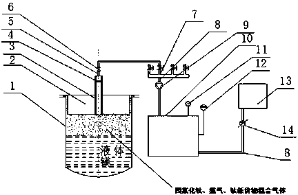
[0018] Such as figure 1 As shown, a reduction device used in the production process of sponge titanium is mainly composed of a reactor 1 and a large cover 2 arranged on it. A standpipe 3 is arranged on the large cover 2, and the standpipe 3 passes through the large cover 2. The cover 2 forms a gas channel, the standpipe 3 is provided with a filter 4, the standpipe 3 is connected to the valve group 7 through the metal hose 5, the metal hose 5 is provided with an automatic pressure relief valve 6, and the valve group 7 passes through the metal pipe 8 Connect with titanium tetrachloride condenser 10, be provided with titanium blower fan 9 therebetween, be respectively provided with exhaust valve 11 and liquid level gauge 12 at the top and side wall of titanium tetrachloride condenser 10, titanium tetrachloride condenser 10 The lower part of one side is connected with the titanium tetrachloride storage tank 13 through a metal pipe 8, and a magnetic drive pump 14 is arranged thereb...


PUM


Abstract

The invention discloses a reducing device for a sponge titanium production process. The reducing device is composed of a reactor and a large cover arranged on the reactor. A vertical pipe is arrangedon the large cover, the vertical pipe passes through the large cover to form a gas channel, a filter screen is arranged in the vertical pipe, and the vertical pipe is connected with a valve group through a metal hose. The metal hose is provided with an automatic pressure relief valve. The valve group is connected with a titanium tetrachloride condenser through a metal pipe. A titanium fan is arranged between the valve group and the titanium tetrachloride condenser. An exhaust valve and a liquid level meter are correspondingly arranged at the top and the side wall of the titanium tetrachloridecondenser, and the lower part of one side of the titanium tetrachloride condenser is connected with a titanium tetrachloride storage tank through a metal pipe, and a magnetic force driving pump is arranged between the titanium tetrachloride condenser and the titanium tetrachloride storage tank. By the adoption of the reducing device, the automatic production degree of sponge titanium can be increased, direct emission of waste gas in the reducing process is avoided, the environment pollution of titanium tetrachloride is reduced, and the recycling of resources is realized.

Description

technical field [0001] The invention relates to a production device of sponge titanium, in particular to a reduction device used in the production of sponge titanium by the magnesium reduction method. Background technique [0002] At present, the industrial production of sponge titanium at home and abroad adopts the Claure method. The main raw materials are magnesium, titanium tetrachloride, and argon. Titanium oxide undergoes a redox reaction with magnesium in the molten state, mainly producing sponge titanium and magnesium chloride. During the production process, it is necessary to fill the appropriate argon protection to prevent the air from entering the reactor to pollute the product. The pressure in the reactor must be kept positive, but the pressure must not be too high and must be controlled within a certain range for production. Tetrachloride Titanium will gasify when it encounters high temperature, and when the pressure in the reactor is too high, manual pressure r...

Claims


Application Information

Patent Timeline
Patent Type & Authority Applications(China)
IPC IPC(8): C22B5/04C22B34/12
CPCC22B5/04C22B34/1272Y02P10/20
Inventor 李剑波郭晓光李斗良李金泽王夕玮龚世成刘进洋尚东
Owner ZUNYI TITANIUM
Learn More