
Narrow-gap TIG welding gun

A narrow gap, welding gun technology, applied in the characteristics of welding rods, welding equipment, welding accessories, etc., can solve the problems of increased filler metal content, increased welding material and energy consumption, and decreased welding efficiency, avoiding increased width and improving reliability. , the effect of compact layout

Pending Publication Date: 2018-08-10
SHENYANG INST OF TECH
View PDF0 Cites 0 Cited by
  • Summary
  • Abstract
  • Description
  • Claims
  • Application Information

AI Technical Summary

Problems solved by technology

In order to ensure that the welding torch has good heat dissipation and achieve the accessibility of the welding torch, a Y-shaped groove must be opened for welding. The angle of the groove needs to be 70°, and the weld seam is wide and deep. Not only the amount of filler metal increases, but also the welding materials and energy consumption. increase, and the welding efficiency decreases, and at the same time, there will be a phenomenon that the side wall is not fused, which will affect the quality of the weld
Obviously, traditional welding methods can no longer meet the needs of these components

Method used


Image

  • Narrow-gap TIG welding gun
  • Narrow-gap TIG welding gun
  • Narrow-gap TIG welding gun

Examples


Embodiment Construction

[0033] The present invention will be further described below in conjunction with the accompanying drawings. The following examples are only used to illustrate the technical solution of the present invention more clearly, but not to limit the protection scope of the present invention.

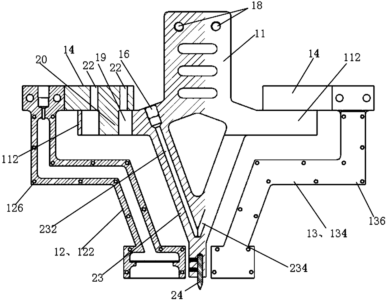
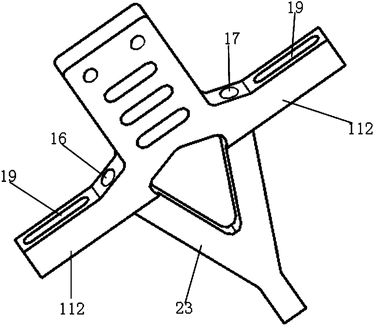
[0034] Such as Figure 2-5 As shown, a narrow gap TIG welding torch includes a welding torch main body 11 provided with a cooling structure 23, a left gas cover 12 and a right gas cover 13 respectively arranged on both sides of the welding torch main body 11, and isolating the welding torch main body 11 and the left gas cover 12 respectively. 1. Two insulating blocks 14 of the welding torch main body 11 and the right gas shield 13, the welding torch main body 11 is provided with a wire connection port 18, and is conductively connected with a tungsten electrode 24 protruding from the bottom end.

[0035] Specifically, the torch main body 11 has a shoulder and is connected to the cooling structur...


PUM

PropertyMeasurementUnit
Thicknessaaaaaaaaaa

Abstract

The invention discloses a narrow-gap TIG welding gun. The narrow-gap TIG welding gun is different from the traditional welding gun, a left air cover and a right air cover are arranged on the two sidesof a welding gun main body correspondingly, due to the fact that the direction is perpendicular to the width direction, the size limit is small, and a large protection space can be achieved; and thedouble-air-cover design is adopted, so that the argon protection effect is also improved. The welding gun main body is internally provided with a cooling structure; and two insulating blocks for separating the welding gun main body from the left air cover and separating the welding gun main body from the right air cover correspondingly are arranged, so that the air covers can be prevented from being electrified, an electrified area can be reduced to the minimum, a ceramic insulation layer does not need to be sprayed on the surface of the whole welding gun, and the situation that the width of the welding gun is increased is avoided. In general, the welding gun has the advantages that the high stability of a traditional TIG welding arc is maintained, the layout is compact, the welding gun and the water cooling are integrated into a whole, the welding gun can be integrally installed on an automatic welding machine, a groove gap can be greatly reduced, so that a lot of welding materials and electric energy consumption are saved, and the welding productivity is improved.

Description

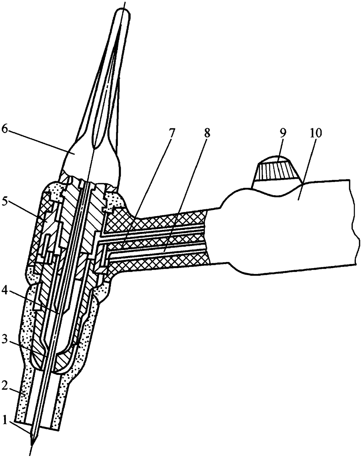
technical field [0001] The invention relates to a welding torch, especially a TIG welding torch. Background technique [0002] Tungsten Inert Gas Welding (TIG) welding torch (hereinafter referred to as TIG welding torch) is used to clamp the tungsten electrode, conduct welding current and transport and spray shielding gas. The structure of the existing water-cooled TIG welding torch is as follows: figure 1 shown. The structure is mainly composed of tungsten electrode 1, ceramic nozzle 2, gas guide sleeve 3, electrode chuck 4, gun body 5, electrode cap 6, air intake pipe 7, cooling water pipe 8, control switch 9, and welding torch handle 10. When welding, in the middle of the argon atmosphere, when the current exceeds 150A, the cooling water pipe 8 is used to cool the gun body, and the air inlet pipe 7 transmits the gas to the ceramic nozzle 2 to spray the protective gas, which plays the role of isolating the air and protecting the molten pool during the welding process ef...

Claims


Application Information

Patent Timeline
IPC IPC(8): B23K9/28B23K9/32B23K9/167
CPCB23K9/167B23K9/28B23K9/285B23K9/32B23K9/325
Inventor 刘家骅王兴张文东冯杨石亨苏政
Owner SHENYANG INST OF TECH
Learn More