Magnetic pole spaced winding combined stator

A combined, magnetic pole technology, applied in the direction of winding, magnetic circuit shape/style/structure, magnetic circuit, etc., can solve the problems of small additional torque, large cogging torque, and inability to realize pole-changing speed change.

Active Publication Date: 2018-08-07
佛山市顺德区致翔金属制品有限公司
View PDF8 Cites 2 Cited by
  • Summary
  • Abstract
  • Description
  • Claims
  • Application Information

AI Technical Summary

Problems solved by technology

[0006] The purpose of the present invention is to overcome the shortcomings of large cogging torque when ordinary brushless DC motors or ordinary permanent magnet synchronous motors adopt integer slot windings, and the shortcomings that asynchronous motors cannot realize pole-changing and speed-changing if centralized windings are used, and provide an effective Conducive to centralized winding processing, small cogging torque when applied to brushless DC motors or permanent magnet synchronous motors, small additional torque generated by tooth harmonic magnetic field when applied to asynchronous motors, and the use of centralized windings can realize Combination Stator with Magnetic Pole Spacing and Winding for Variable Pole and Variable Speed ​​Asynchronous Motor

Method used


Image

  • Magnetic pole spaced winding combined stator
  • Magnetic pole spaced winding combined stator
  • Magnetic pole spaced winding combined stator

Examples


Embodiment Construction

[0061] The present invention is further described below in conjunction with accompanying drawing.

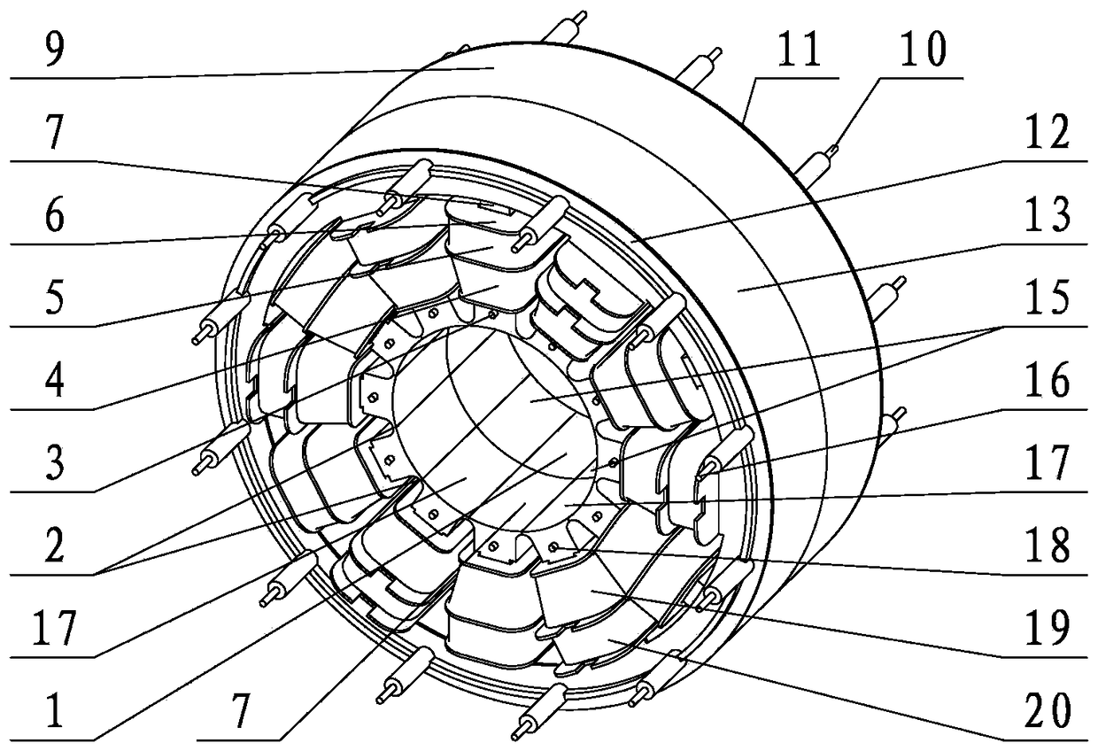
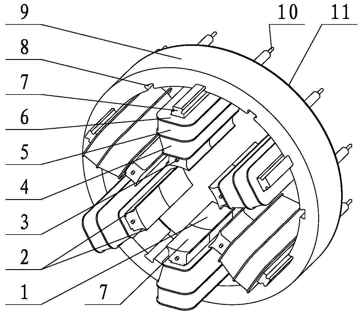
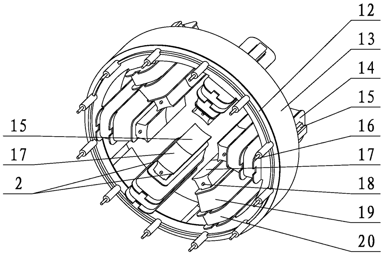
[0062] refer to figure 1 , figure 2 , image 3 , the combined stator includes stator part one and stator part two. Stator part 1 includes stator iron core 9 , magnetic pole insert 7 , positioning pin 3 , ring-shaped coil bobbin 11 , coil bobbin 6 , and welding pin 10 . The annular bobbin 11 includes several positioning bobbins 27, and each positioning bobbin 27 and bobbin 6 respectively have one or several bobbin slots, if each positioning bobbin 27 and bobbin 6 There is a skeleton wire groove respectively, then stator part one also includes coil one, if each positioning coil skeleton one 27 and coil skeleton one 6 have two skeleton wire slots respectively, then stator part one also includes inner coil one 4, outer coil a 5. The second stator component includes a second stator core 13 , a second magnetic pole insert 15 , a second positioning pin 18 , a second annular coil ...


PUM


Abstract

The present invention relates to a motor stator, in particular, a magnetic pole spaced winding combined stator. The magnetic pole spaced winding combined stator includes a stator component A and a stator component B; the stator magnetic poles of which the serial numbers are odd numbers, of the stator component A and the stator component B and the stator magnetic poles of which the serial numbers are even numbers, of the stator component A and the stator component B, are arranged alternately; in the winding machining process of a concentrated winding, a large machining operation space is provided between two adjacent stator magnetic poles, and therefore, the slot opening width of stator core wire slots can be reduced under a condition that the winding machining of the concentrated winding is not affected, or closed slots can be adopted as the stator core wire slots, and therefore, a cogging torque can be lowered, a brushless direct-current motor or permanent magnetic synchronous motor can use integer-slot windings, the selection range of the number of slots and the number of poles in the design of the brushless direct-current motor or the permanent magnet synchronous motor can be extended, and the performance of the motor can be improved. The combined stator can realize pole variation and speed variation when applied to an asynchronous motor, so that the asynchronous motor can be facilitated to decrease an additional torque generated by a tooth harmonic magnetic field, and therefore, the efficiency of the motor can be improved.

Description

technical field [0001] The present invention is a magnetic pole spaced winding combined stator, which relates to a motor stator, in particular to a concentrated winding coil sequentially wound on the iron core pole body and the magnetic pole insert of two stator iron cores, And the magnetic pole inserts of the two stator cores are alternately inserted into the motor stator of the tongue and groove between two adjacent iron core pole bodies of the opposite stator core. Background technique [0002] The motor stator winding coil is divided into two structural types: distributed winding and concentrated winding. Most asynchronous motors use distributed windings, while brushless DC motors (BLDC) and permanent magnet synchronous motors (PMSM) use centralized windings. The processing technology of distributed winding is complicated, and the processing technology of centralized winding is simple. The interphase insulation strength of centralized winding is higher than that of dis...

Claims


Application Information

Patent Timeline
IPC IPC(8): H02K1/14H02K1/16H02K3/52
CPCH02K1/148H02K1/165H02K3/522H02K2201/15
Inventor 赵晓东
Owner 佛山市顺德区致翔金属制品有限公司
Why Eureka
Try Eureka