Tyre

A tire and tire circumferential technology, applied in the direction of heavy tires, tire parts, tire tread/tread pattern, etc., can solve problems such as pattern block cracks, and achieve the effect of improving rolling resistance performance

Active Publication Date: 2019-06-21
SUMITOMO RUBBER IND LTD
View PDF10 Cites 0 Cited by
  • Summary
  • Abstract
  • Description
  • Claims
  • Application Information

AI Technical Summary

Problems solved by technology

Therefore, there will be a new problem that cracks are likely to occur at the bottom of the horizontal groove, especially at the root of the pattern block.

Method used


Image

  • Tyre
  • Tyre
  • Tyre

Examples


Embodiment Construction

[0044] Hereinafter, an embodiment of the present invention will be described with reference to the drawings.

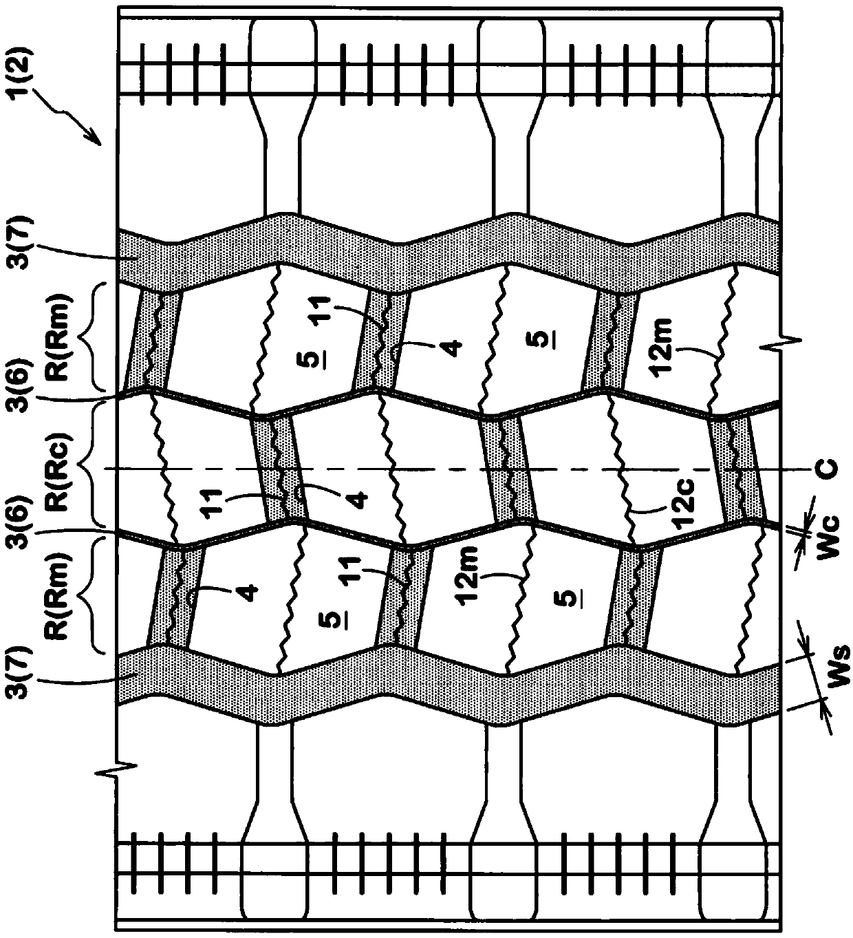
[0045] figure 1 It is a developed view showing the tread portion 2 of the tire 1 according to the embodiment of the present invention. In this embodiment, a case where the tire 1 is formed as a heavy-duty pneumatic tire is shown. However, it can also be formed as various tires such as pneumatic tires for passenger cars, commercial vehicles, etc., and non-pneumatic tires (for example, airless tires) in which pressurized air is not filled inside the tires.

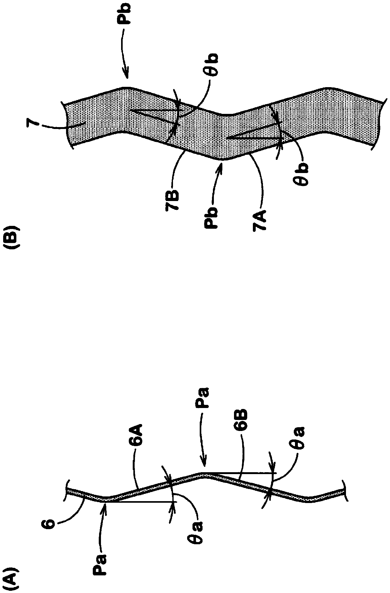
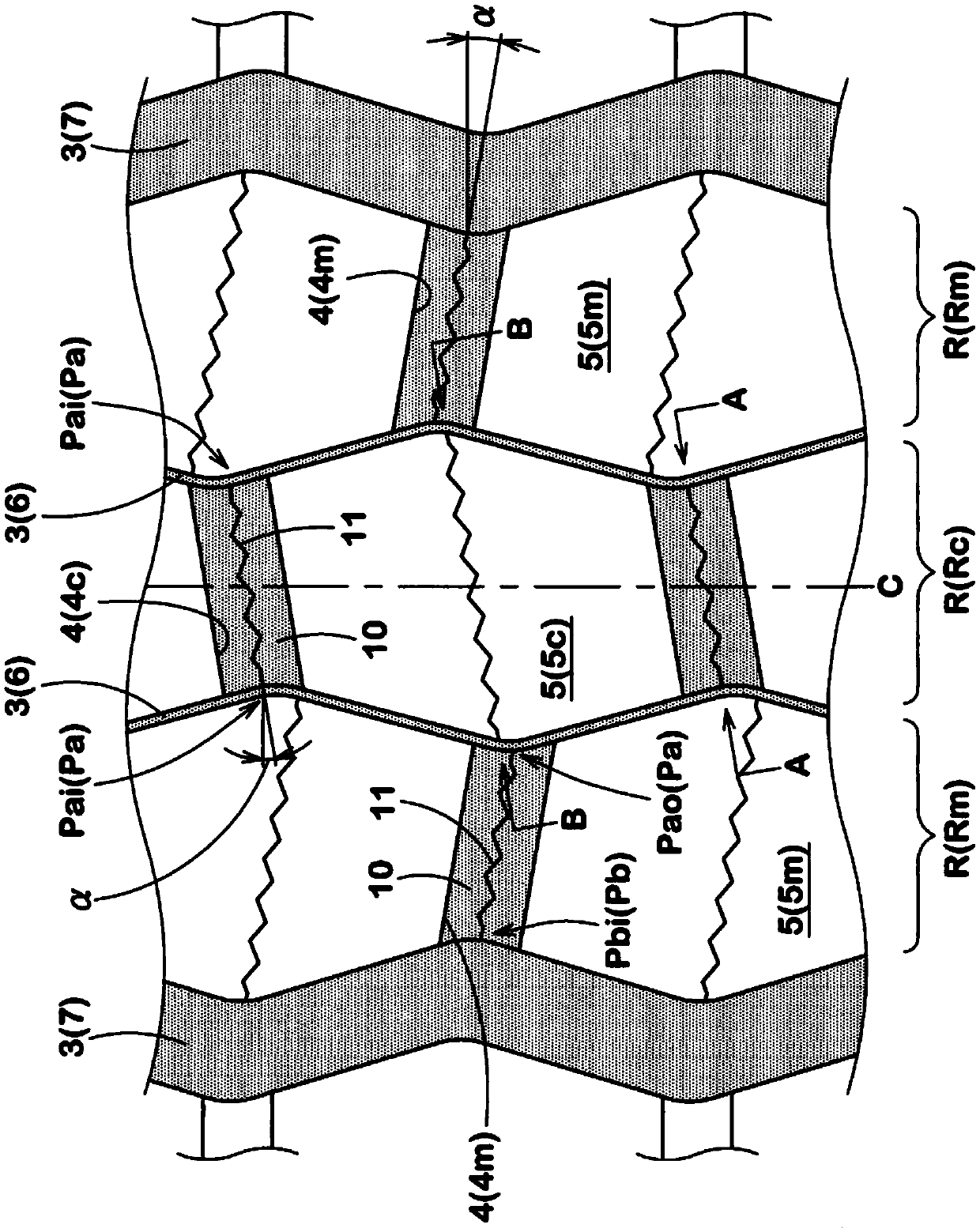
[0046] Such as figure 1 As shown, the tire 1 includes four zigzag circumferential grooves 3 extending in a zigzag shape on the tread portion 2 in the tire circumferential direction. In addition, the tread portion 2 is provided with a transverse groove 4 for connecting between the sawtooth circumferential grooves 3, 3 adjacent in the tire axial direction, whereby the land portion R between the sawtooth circumferen...


PUM


Abstract

A tyre with reduced rolling resistance is provided. The tyre includes four zigzag circumferential grooves (3) and hexagonal blocks (5) divided by the lateral grooves (4) each extending so as to connect between adjacent ones (3,3) of the zigzag circumferential grooves (3). The zigzag circumferential grooves (3) include a pair of center circumferential grooves (6) each having a groove width not morethan 4.0 mm and a pair of shoulder circumferential grooves (7) each having a groove width larger than that of each of the center circumferential grooves (6). A depth (D1) of each of the lateral grooves (4) is smaller than a depth (D0) of each of the zigzag circumferential grooves (3), and a groove bottom (10) of each of the lateral grooves (4) is provided with a first sipe (11).

Description

technical field [0001] The present invention relates to a tire with reduced rolling resistance. Background technique [0002] For example, Patent Document 1 below discloses a heavy duty tire in which a plurality of hexagonal blocks are provided on a tread portion. The tire has a pair of central circumferential grooves and a pair of shoulder circumferential grooves extending in a zigzag shape in the tire circumferential direction. Furthermore, the land portion between the central circumferential grooves and the land portion between the central circumferential groove and the shoulder circumferential groove are divided into hexagonal blocks by the transverse grooves connecting the crests of the serrations. [0003] Such a hexagonal block has a wide center portion of the block and large inner angles at each corner. Therefore, the deformation from the start to the end of the ground contact is small, and the rolling resistance performance is excellent. [0004] However, further...

Claims


Application Information

Patent Timeline
Patent Type & Authority Applications(China)
IPC IPC(8): B60C11/03B60C11/12
CPCB60C11/125B60C11/11B60C2011/0346Y02T10/86B60C11/0306B60C11/1236B60C11/1218B60C11/1259B60C2200/06B60C2011/0355B60C2011/0367B60C2011/0348B60C2011/1213B60C2011/1231B60C2011/0353B60C11/1263
Inventor 井藤佳惠
Owner SUMITOMO RUBBER IND LTD
Why Eureka
Try Eureka