
Detection method of hydraulic cylinder

A technology of a hydraulic cylinder and a detection method, which is applied in the field of hydraulic cylinder detection, can solve the problems of difficulty in detecting tiny leaks of seals, leakage of oil cylinders, and low detection rate of unqualified products, and achieves low production and maintenance costs. The effect of reducing the failure rate, convenient and efficient operation

Pending Publication Date: 2018-08-03
龙工(福建)液压有限公司
View PDF0 Cites 3 Cited by
  • Summary
  • Abstract
  • Description
  • Claims
  • Application Information

AI Technical Summary

Problems solved by technology

The problem with this detection method is that it is difficult to detect small seal leakage
Even though most hydraulic cylinder test benches are equipped with pressure detection devices to monitor the pressure loss in the inner cavity of the cylinder during the pressure maintaining process, the detection rate of unqualified products is still not high. After using for a period of time, the problem of leakage of the oil cylinder can be gradually reflected

Method used


Image

  • Detection method of hydraulic cylinder

Examples


Embodiment Construction

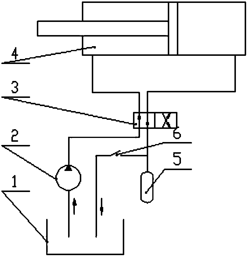
[0015] A hydraulic cylinder detection method of the present invention will be described in further detail below in conjunction with the accompanying drawings and specific embodiments.

[0016] figure 1 As shown, a hydraulic cylinder detection method of the present invention is based on the existing no-load hydraulic cylinder detection pressure test bench, after connecting a tee on the oil return pipeline behind the electromagnetic reversing valve 3, and connecting the ball valve 6 all the way It is then connected to the oil return tank 1, and the other road is connected to the accumulator 5 as a load source to realize artificially adding controllable pressure in the corresponding cavity of the hydraulic cylinder 4 to simulate the load. The accumulator is a piston type accumulator, model HXQ-L20 / 31.5, it is a kind of hydraulic isolation accumulator, its working principle is to use the compressibility of gas, separate the gas and liquid through the piston, and pre-charge the sta...


PUM


Abstract

The invention discloses a detection method of a hydraulic cylinder. A tee is connected to an oil return pipe behind a solenoid directional valve of an existing hydraulic cylinder detection pressure testing platform, one way is connected with a ball valve and then is connected with an oil return tank, and the other way is connected with an energy accumulator as a load source, so that controlled pressure is manually added to a corresponding die cavity of the oil cylinder for artificial load; during operation, the to-be-detected oil cylinder is installed on the pressure testing platform, and thepressure value of the energy accumulator is set; then the ball valve is closed, a hydraulic pump is started, hydraulic oil is driven into a front cavity of the oil cylinder by the hydraulic pump, a back cavity of the oil cylinder is directly connected with the energy accumulator at the moment, the pressure of the energy accumulator is adjusted to the set value, therefore, the pressure of the hydraulic oil in the back cavity of the oil cylinder is consistent with the set value of the load, and the load value is obtained by multiplying the pressure by the sectional area; then the solenoid directional valve is operated, and the oil return pipe is still connected with the energy accumulator so as to achieve a loading effect; and after the pressure test is finished, the ball valve is opened, the pressure of the oil return pipe is relieved, and the hydraulic cylinder is removed. The detection method has the characteristics of low manufacturing and maintenance cost and convenience and high efficiency in operation, and the factory reject ratio of the oil cylinder can be obviously reduced.

Description

technical field [0001] The invention relates to a pressure test detection method of hydraulic equipment, in particular to a hydraulic oil cylinder detection method. Background technique [0002] Hydraulic cylinders are widely used in the field of construction machinery. For the quality of the hydraulic cylinder, the most important thing is the sealing ability of each cavity of the cylinder to the hydraulic oil. Only when the sealing parts inside the hydraulic cylinder fail, will there be a failure. At present, the ex-factory inspection of the quality of hydraulic cylinders generally adopts when the hydraulic cylinder is unloaded, and it is judged whether the hydraulic cylinder is qualified by the back and forth driving of the hydraulic cylinder and the pressure holding of 1.5 times the rated pressure; Without increasing the load, the hydraulic oil is output from the hydraulic pump to the front chamber of the hydraulic cylinder, and at this time the oil in the rear chamber d...

Claims


Application Information

Patent Timeline
IPC IPC(8): F15B19/00
CPCF15B19/00F15B2211/855
Inventor 应剑俞冬亮
Owner 龙工(福建)液压有限公司
Learn More