
Excimer laser device

A technology of excimer laser and laser gas, which is applied in the direction of lasers, phonon exciters, laser components, etc., can solve the problem of resolution reduction

Active Publication Date: 2018-07-31
AURORA ADVANCED LASER CO LTD
View PDF11 Cites 2 Cited by
  • Summary
  • Abstract
  • Description
  • Claims
  • Application Information

AI Technical Summary

Problems solved by technology

As a result, resolution may decrease

Method used


Image

  • Excimer laser device
  • Excimer laser device
  • Excimer laser device

Examples


Embodiment Construction

[0070] content

[0071] 1. Summary

[0072] 2. Excimer laser device of comparative example

[0073] 2.1 Structure

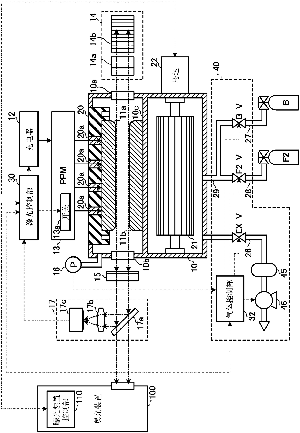
[0074] 2.1.1 Laser oscillation system

[0075] 2.1.2 Laser gas control system

[0076] 2.2 Action

[0077] 2.2.1 Operation of laser oscillation system

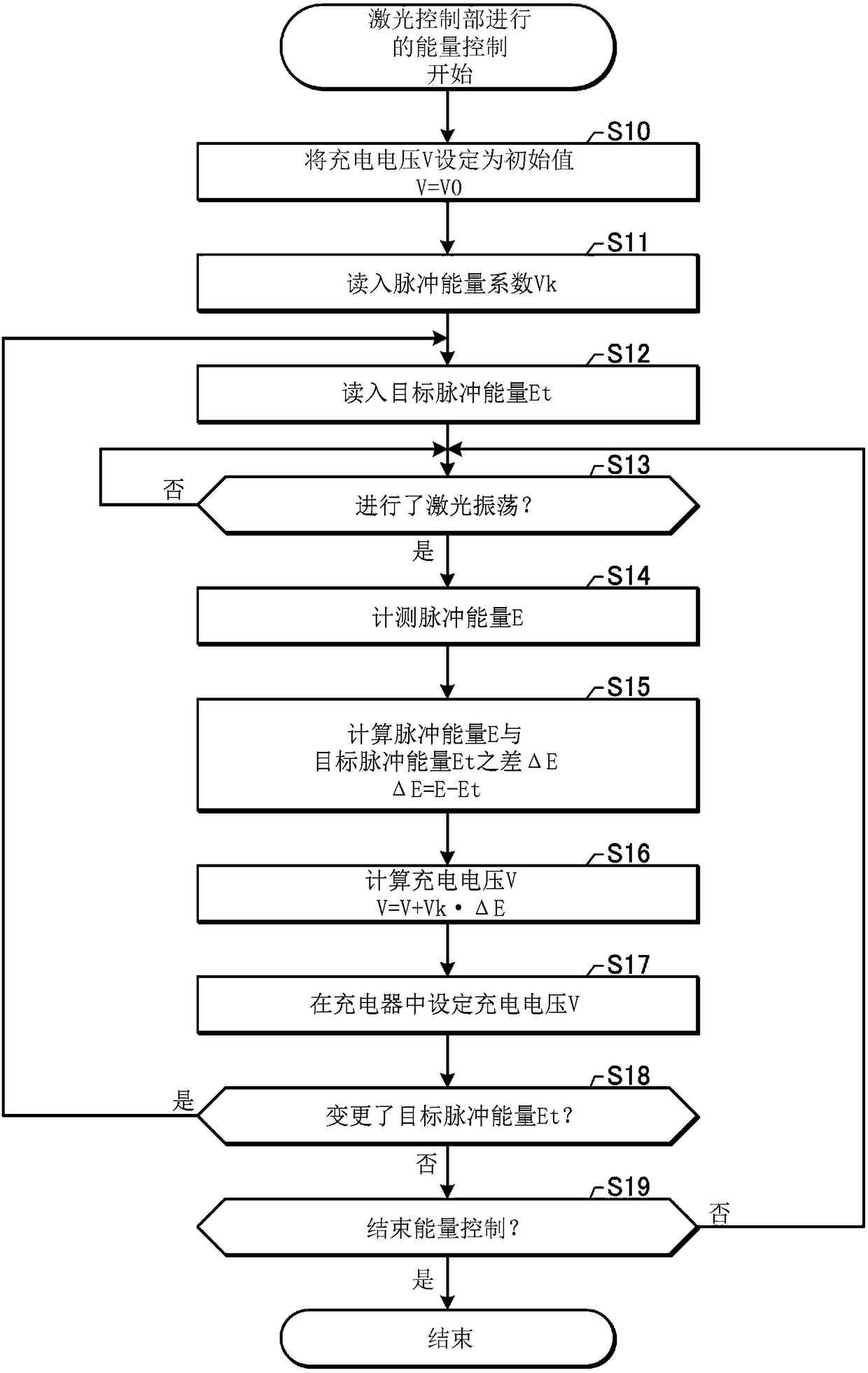
[0078] 2.2.2 Energy Control

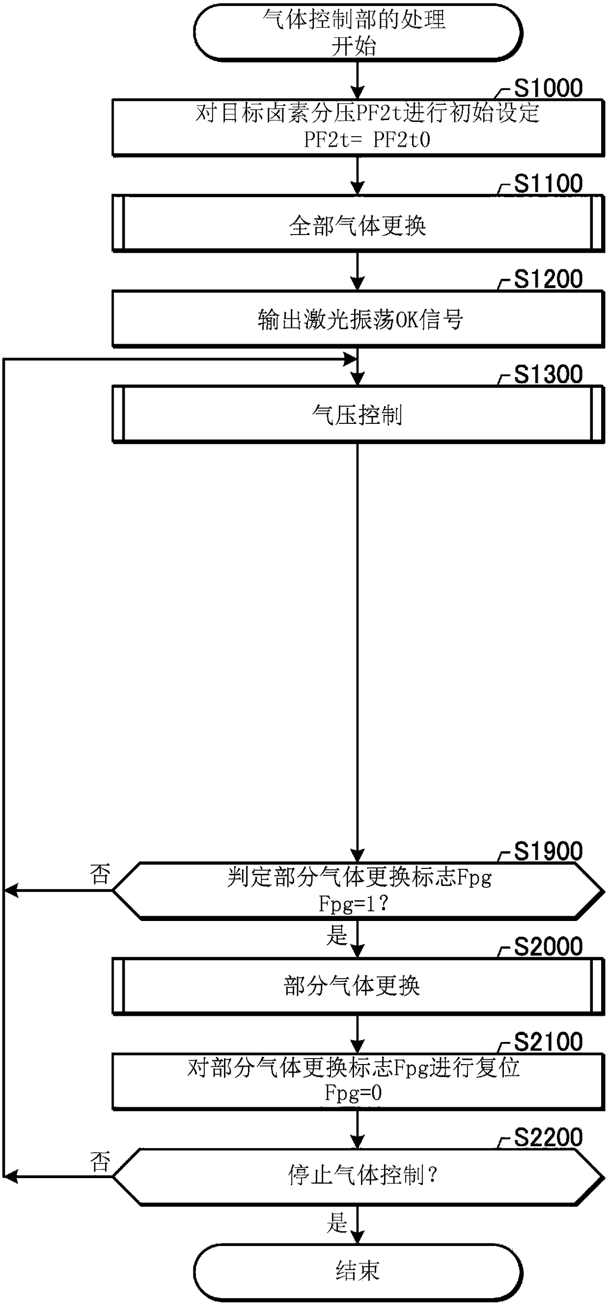
[0079] 2.2.3 Laser gas control

[0080] 2.2.3.1 Full gas replacement

[0081] 2.2.3.2 Air pressure control

[0082] 2.2.3.3 Measurement of the number of shots

[0083] 2.2.3.4 Partial gas replacement

[0084] 2.3 Topics

[0085] 3. An excimer laser device that detects energy reduction and adjusts the partial pressure of halogen gas

[0086] 3.1 Structure

[0087] 3.2 Action

[0088] 3.2.1 Detection of energy reduction

[0089] 3.2.1.1 First example of processing for counting the number of times Nd of energy down detections

[0090] 3.2.1.2 Second example of processing for counting the number of times Nd of energy down detections

[0091] 3.2.1.3 The third example of ...


PUM


Abstract

An excimer laser device is provided with: an optical resonator; a chamber positioned in the optical resonator, the chamber including a pair of discharge electrodes and accommodating a laser gas; a power supply for receiving a trigger signal and applying a pulsed voltage to the pair of discharge electrodes on the basis of the trigger signal; an energy monitor for measuring the pulse energy of pulsed laser light outputted from the optical resonator; a halogen gas partial pressure regulation unit configured so as to be capable of exhausting some of the laser gas accommodated in the chamber and supplying the laser gas into the chamber; and a control unit for acquiring the result of the pulse energy measurements performed by the energy monitor, detecting an energy dip on the basis of the pulseenergy measurement result, and controlling the halogen gas partial pressure regulation unit on the basis of the result of detecting an energy dip, whereby the halogen gas partial pressure in the chamber is adjusted.

Description

technical field [0001] The present invention relates to excimer laser devices. Background technique [0002] In recent years, in semiconductor exposure apparatuses (hereinafter referred to as “exposure apparatuses”), improvement in resolution has been demanded along with miniaturization and high integration of semiconductor integrated circuits. Therefore, the shortening of the wavelength of the light emitted from the light source for exposure is progressing. Generally, a gas laser device is used as a light source for exposure instead of a conventional mercury lamp. For example, as a gas laser device for exposure, a KrF excimer laser device that outputs ultraviolet laser light with a wavelength of 248 nm and an ArF excimer laser device that outputs ultraviolet laser light with a wavelength of 193 nm are used. [0003] As a new-age exposure technology, liquid immersion exposure in which the gap between the exposure lens on the exposure device side and the wafer is filled wit...

Claims


Application Information

Patent Timeline
Patent Type & Authority Applications(China)
IPC IPC(8): H01S3/225H01S3/036H01S3/134
CPCH01S3/225H01S3/036H01S3/08009H01S3/2366H01S3/134H01S3/09702H01S3/1305H01S3/038
Inventor 藤卷洋介对马弘朗池田宏幸若林理
Owner AURORA ADVANCED LASER CO LTD
Learn More