Optical-path sensitive-type accelerometer
An accelerometer and sensitive technology, applied in the direction of measuring acceleration, multi-dimensional acceleration measurement, speed/acceleration/impact measurement, etc., can solve the problems of high cost, large three-axis orthogonality error, and large volume, and achieve low cost and measurement Improved resolution and smaller size
- Summary
- Abstract
- Description
- Claims
- Application Information
AI Technical Summary
Problems solved by technology
Method used
Image
Examples
Embodiment 1
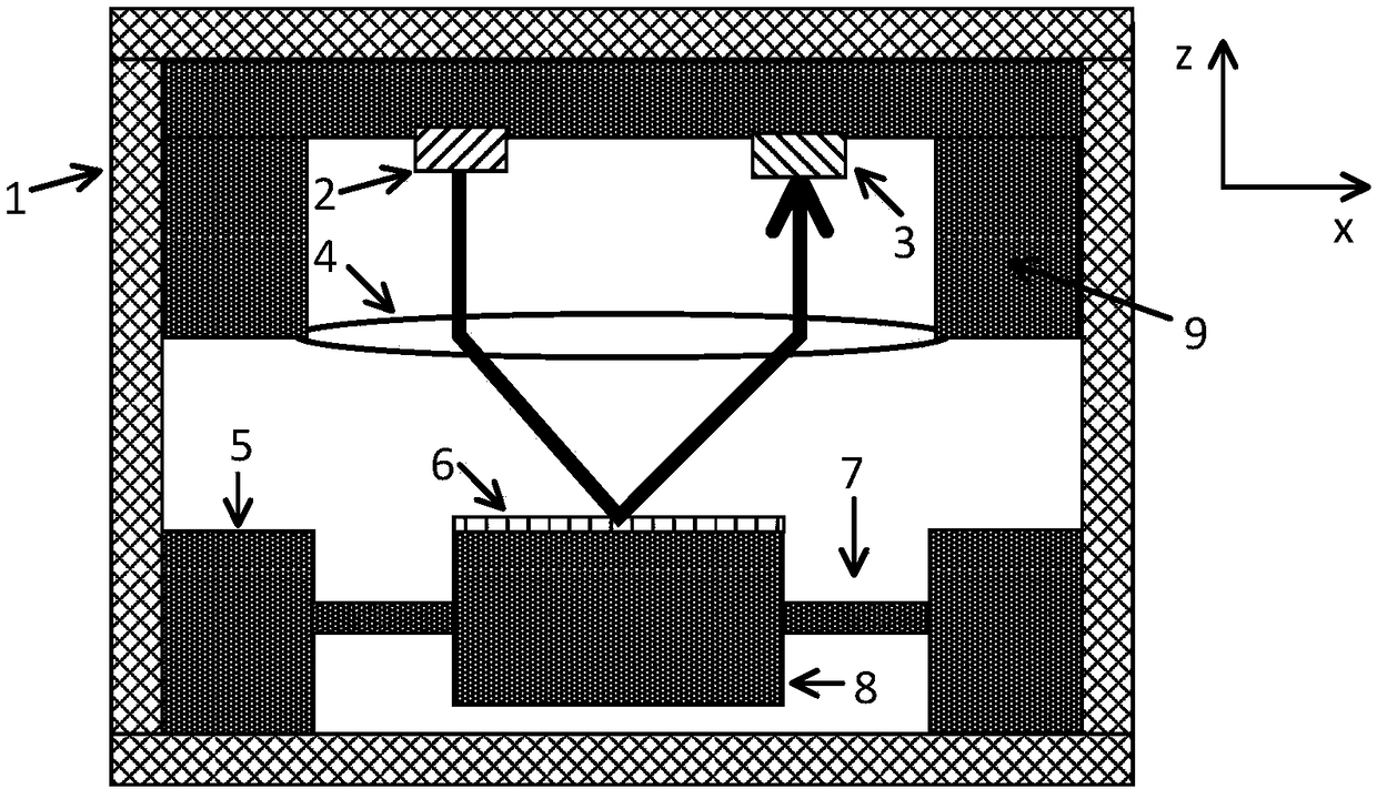
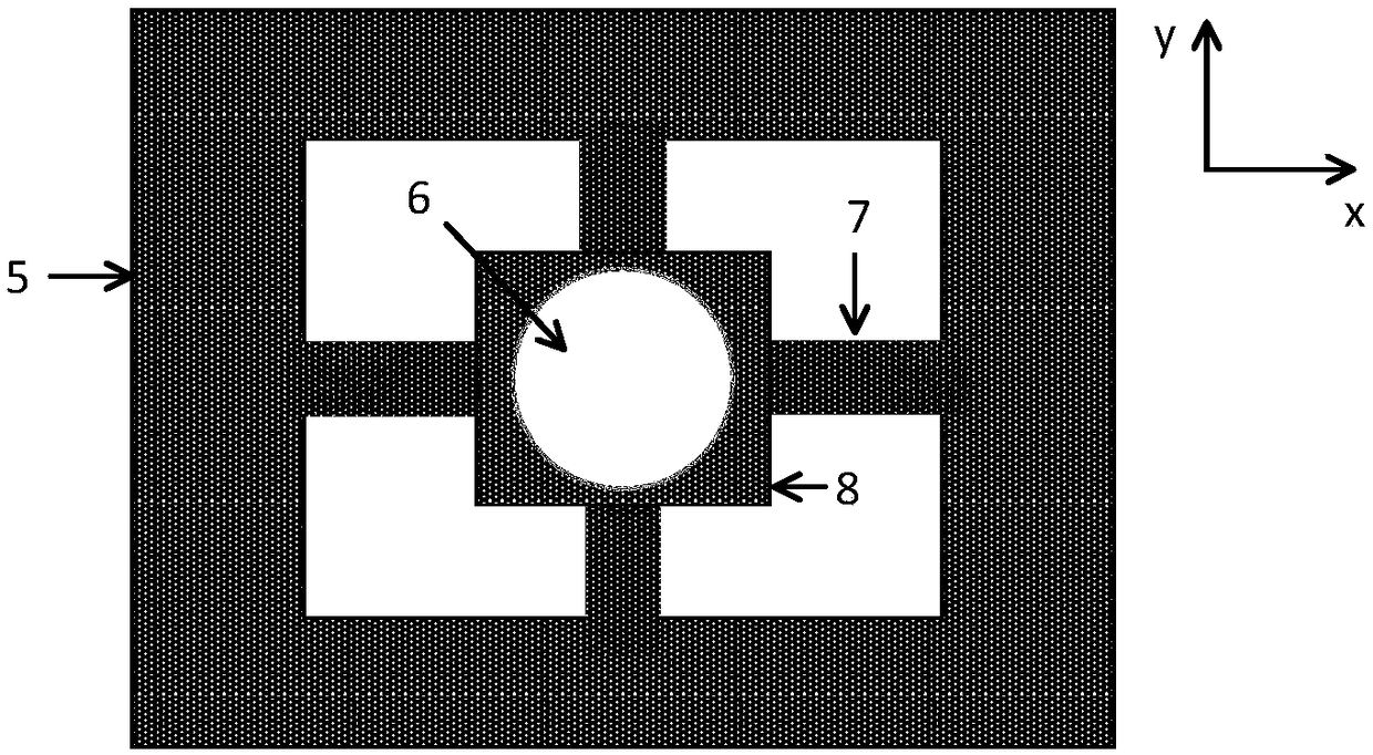
[0042] Embodiment 1 of the present invention provides an optical path-sensitive accelerometer, including a light source 2 , a photodetector 3 , a lens 4 and a first MEMS chip, wherein the first MEMS chip includes a mirror 6 , a support beam 7 and a mass 8 ; The mirror 6 is arranged on the mass block 8, and the mass block 8 is connected with the support beam 7, and under the action of acceleration, the support beam 7 causes the mass block 8 to be displaced along the Z-axis direction;
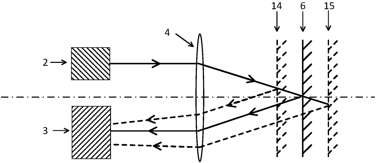
[0043] The lens 4 is placed between the plane where the light source 2 and the photodetector 3 are located and the plane where the reflector 6 is located;
[0044] The photodetector 3 is used to receive the light generated by the light source 2 , the optical path adjusted by the lens 4 , and finally reflected back by the reflector 6 .
[0045] The invention provides an optical path sensitive accelerometer, which utilizes the optical path loss caused by the axial displacement of the reflecting mir...
Embodiment 2
[0054] In many applications, it is necessary to monitor three-dimensional acceleration at the same time. Traditional accelerometers are mainly single-axis sensors. Three single-axis accelerometers need to be assembled to form a three-dimensional accelerometer, which will result in a large error in three-axis orthogonality and a large volume. ,high cost. In order to overcome this technical problem, this Embodiment 2 makes some improvements on the basis of Embodiment 1, so that not only the acceleration in the Z direction can be measured by the displacement of the mass block 8 , but also X and Y can be measured by the rotation of the mass block 8 directional acceleration, that is, three-dimensional acceleration can be monitored simultaneously without assembly. The main difference from Embodiment 1 is that in Embodiment 2, the PD array 10 is used to replace the original photodetector 3 to detect the position and shape of the light spot; at the same time, the X-axis support beam 1...
Embodiment 3
[0067] In order to better understand the principle of the optical path-sensitive accelerometer of the present invention, on the basis of Embodiment 2, Embodiment 3 provides a specific use and measurement method of the above-mentioned accelerometer. An optical path-sensitive accelerometer provided in this embodiment 2 uses a PD array to receive reflected light, and the moving path of the light spot and the size of the light spot can be detected. It is mainly used for simultaneous measurement of acceleration in three-dimensional directions, that is, X, Y and Z directions. Among them, the rotation of the mass block 8 along X and Y will cause the position of the light spot to change, while the shape of the light spot is basically unchanged; the displacement of the mass block 8 in the Z direction will cause the mirror 6 to deviate from the focal plane of the lens 4, and then reflect The spot size onto the PD array 10 changes.
[0068] The measurement and use method of the accelero...
PUM
 Abstract
Description
Claims
Application Information
 - R&D Engineer
- R&D Manager
- IP Professional
- Industry Leading Data Capabilities
- Powerful AI technology
- Patent DNA Extraction
Browse by: Latest US Patents, China's latest patents, Technical Efficacy Thesaurus, Application Domain, Technology Topic, Popular Technical Reports.
© 2024 PatSnap. All rights reserved.Legal|Privacy policy|Modern Slavery Act Transparency Statement|Sitemap|About US| Contact US: help@patsnap.com


