Heat-conducting property steady-state test method for sheet materials
A test method and thin sheet technology, applied in the direction of material thermal conductivity, material thermal expansion coefficient, etc., can solve the problems of low total heat flow power, difficult to ensure heat flow uniformity and continuity, poor test accuracy and repeatability, etc., to reduce the surface area. Effects of heat loss, improved stability and repeatability, improved accuracy
- Summary
- Abstract
- Description
- Claims
- Application Information
AI Technical Summary
Problems solved by technology
Method used
Image

Examples
Embodiment approach 1
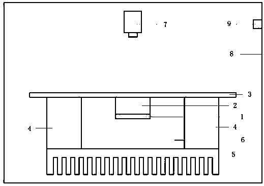
[0027] The cross-sectional structure of the test system is as follows: figure 1 As shown: the electric heating device 1 locally heats the middle part of the thin slice 3 to be tested with a constant power through the heat conducting column 2, and the heat flows to the heat sink 5 through the heat conducting ring seat 4; the surroundings of the electric heating device 1 and the heat conducting column 2, and the thin slice 3 The lower part is filled with heat-insulating material 6; the thermal imager 7 is facing the sheet 3 to be tested; the main body of the test device is located in the thermostat 8, and the temperature sensor 9 measures the temperature of the thermostat.
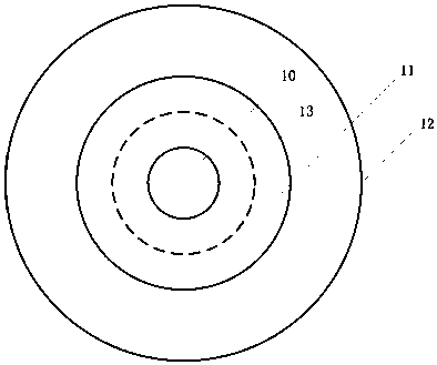
[0028] The surface area of the sample is divided into figure 2 As shown: the heating area 10 is located in the middle of the sample, the test area 11 surrounds the heating area, and the heat dissipation area 12 is located on the outermost side; both the heating area 10 and the heat dissipation area 12 hav...
Embodiment approach 2
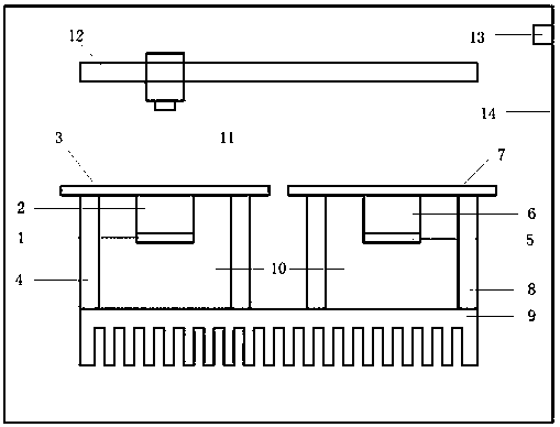
[0046] The cross-sectional structure of the test system is as follows: image 3 As shown: the main electric heating device 1 locally heats the middle part of the thin slice 3 to be tested with a constant power through the main heating column 2, and the heat flows to the heat sink 9 through the heat conducting ring seat 4; symmetrically, the reference electric heating device 5 passes through the reference heat conducting column 6 pair The reference sheet 7 is locally heated with a constant power, and the heat flows through the heat conduction ring seat 8 to the heat sink 9; around the main electric heating device 1 and the main heat column 2, the lower part of the sheet 3 to be measured, the reference electric heating device 5 and the reference heat conduction The surroundings of the column 6 and the lower part of the reference sheet 7 are filled with heat insulating material 10; the thermal imager 11 is installed on a one-dimensional translation platform 12, and can move back a...
Embodiment approach 3
[0064] The cross-sectional structure of the test system is as follows: Figure 5 As shown: the sheet 3 to be tested is arranged on the heat conducting ring seat 4, and the laser light emitting part 1 is fixed on the two-dimensional electric displacement table 2, which can emit a circular spot laser with a diameter of 2 mm at a constant power and project it on the lower surface of the sheet 3 to be tested; After the test sheet is heated, the heat flows through the heat conduction ring seat 4 to the heat sink 5; the thermal imager 6 is located directly above the test sheet 3; the main body of the test device is located in the thermostat 7, and the temperature sensor 8 measures the temperature of the thermostat.
[0065] The surface thermal conductivity of the thin slice 3 to be tested is unevenly distributed. According to the resolution, the surface needs to be divided into a series of non-overlapping single-connected regions, such as equidistant grids, or properly adjusted accor...
PUM
 Abstract
Description
Claims
Application Information
 - R&D
- Intellectual Property
- Life Sciences
- Materials
- Tech Scout
- Unparalleled Data Quality
- Higher Quality Content
- 60% Fewer Hallucinations
Browse by: Latest US Patents, China's latest patents, Technical Efficacy Thesaurus, Application Domain, Technology Topic, Popular Technical Reports.
© 2025 PatSnap. All rights reserved.Legal|Privacy policy|Modern Slavery Act Transparency Statement|Sitemap|About US| Contact US: help@patsnap.com