Crank-arm-type overhead working truck connector levelling hydraulic system

An aerial work vehicle and hydraulic system technology, applied in the field of hydraulic control, can solve the problems of partial vacuum, hidden dangers, inclination of the working platform 13, etc., and achieve the effect of ensuring synchronous movement

Pending Publication Date: 2018-07-13
HUNAN SINOBOOM HEAVY IND
View PDF0 Cites 14 Cited by
  • Summary
  • Abstract
  • Description
  • Claims
  • Application Information

AI Technical Summary

Problems solved by technology

[0002] like figure 1 When the crank arm type aerial work vehicle shown is moving the folding arm 12 up and down, the airtight cavity formed by the connection between the rod chamber of the folding arm luffing cylinder 6 and the rodless chamber of the connecting body leveling cylinder 7 realizes The synchronous linkage of the two oil cylinders ensures that the working platform 13 and the connecting body 15 between the folding arm 12 and the main arm 14 are always in a translational state. The temperature of the oil in the airtight cavity of the connecting body leveling cylinder 7 drops, and the volume of the oil shrinks to a certain extent, forming a partial vacuum, which directly causes the folding arm luffing cylinder 6 to be pulled out suddenly when the working platform is loaded in the shutdown state. It will cause great damage to the operator and equipment, or when the machine is started again and the arm is folded and the amplitude is changed, the expansion and contraction of the connecting body leveling cylinder 7 lags behind, causing the working platform 13 to tilt, which has certain potential safety hazards

Method used


Image

  • Crank-arm-type overhead working truck connector levelling hydraulic system
  • Crank-arm-type overhead working truck connector levelling hydraulic system
  • Crank-arm-type overhead working truck connector levelling hydraulic system

Examples


Embodiment approach

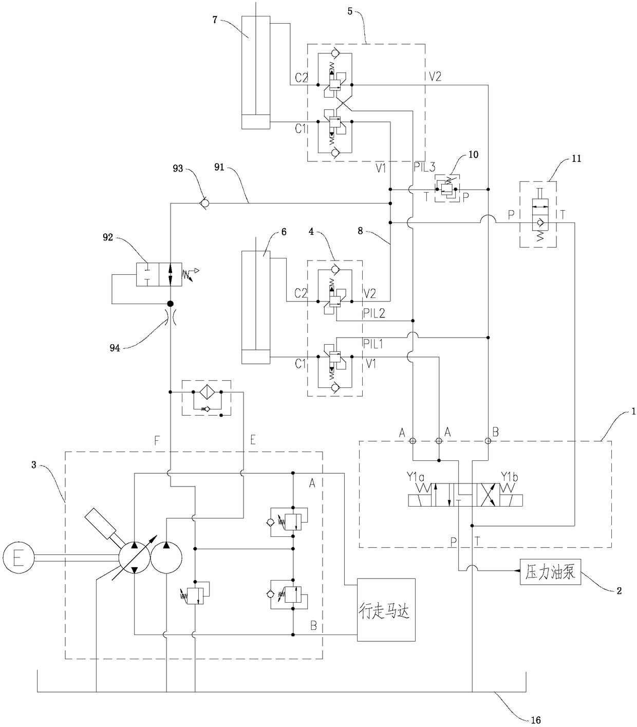
[0037] More preferably, refer to image 3 , the control valve 92 is an oil replenishing solenoid valve, and an electric control box 921 is arranged on the oil replenishing solenoid valve, and the electric control box 921 is electrically connected with the oil replenishing solenoid valve. This is the second implementation of the control valve 92. The staff inputs the program to the electric control box 921 to control the opening delay time of the electric control box 921. The delay time in this implementation is 5s. When starting up again after stopping, the electric control box 921 controls the oil supply solenoid valve to be energized, the oil supply solenoid valve spool reverses direction, and the oil supply line 91 is turned on. The reversing makes the oil supply line 91 cut off, avoiding the oil line of the oil charge pump from being connected with the closed cavity all the time, and realizing the automatic closing of the oil supply work.

[0038] Further preferably, a fo...


PUM


Abstract

The invention discloses a crank-arm-type overhead working truck connector levelling hydraulic system which comprises a traveling oil pump, a hydraulic oil tank, a pressure oil pump, an electromagneticreversing valve, a connector levelling oil cylinder and a folding-arm amplitude-change oil cylinder. An oil inlet P, a working port A, a working port B and a return port T are formed in the electromagnetic reversing valve. The oil inlet P and the pressure oil pump communicate, and the return port T and the hydraulic oil tank communicate. A rod cavity of the folding-arm amplitude-change oil cylinder communicates with a rodless cavity of the connector levelling oil cylinder through a first connecting pipeline, and the working port A communicates with a rodless cavity of the folding-arm amplitude-change oil cylinder through a second connecting pipeline. A rod cavity of the connector levelling oil cylinder communicates with the working port B through a third connecting pipeline. An oil compensating loop is arranged on the first connecting pipeline, one end of the oil compensating loop communicates with the first connecting pipeline, and the other end of the oil compensating loop communicates with the traveling oil pump. Synchronous movement of the folding-arm amplitude-change oil cylinder and the connector levelling oil cylinder is effectively kept, and the crank-arm-type overhead working truck connector levelling hydraulic system is applied to the field of hydraulic control.

Description

technical field [0001] The invention relates to the field of hydraulic control, in particular to a connecting body leveling hydraulic system of an articulating arm type aerial work vehicle. Background technique [0002] like figure 1 When the crank arm type aerial work vehicle shown is moving the folding arm 12 up and down, the airtight cavity formed by the connection between the rod chamber of the folding arm luffing cylinder 6 and the rodless chamber of the connecting body leveling cylinder 7 realizes The synchronous linkage of the two oil cylinders ensures that the working platform 13 and the connecting body 15 between the folding arm 12 and the main arm 14 are always in a translational state. The temperature of the oil in the airtight cavity of the connecting body leveling cylinder 7 drops, and the volume of the oil shrinks to a certain extent, forming a partial vacuum, which directly causes the folding arm luffing cylinder 6 to be pulled out suddenly when the working p...

Claims


Application Information

Patent Timeline
Patent Type & Authority Applications(China)
IPC IPC(8): F15B11/08F15B13/02B66F11/04
CPCF15B11/08F15B13/02B66F11/04
Inventor 刘国良赵俊波吴宇佳李达之石伟
Owner HUNAN SINOBOOM HEAVY IND
Why Eureka
Try Eureka