Side-blowing spray gun
A spray gun and pipeline technology, applied in the field of metallurgy, can solve the problems of small size design of the furnace body, increase the outlet speed of the oxygen injection lance, and the limited stirring effect of the molten pool, etc., so as to delay the time of upward flow and residence time The effect of prolonging and increasing the stirring area
- Summary
- Abstract
- Description
- Claims
- Application Information
AI Technical Summary
Problems solved by technology
Method used
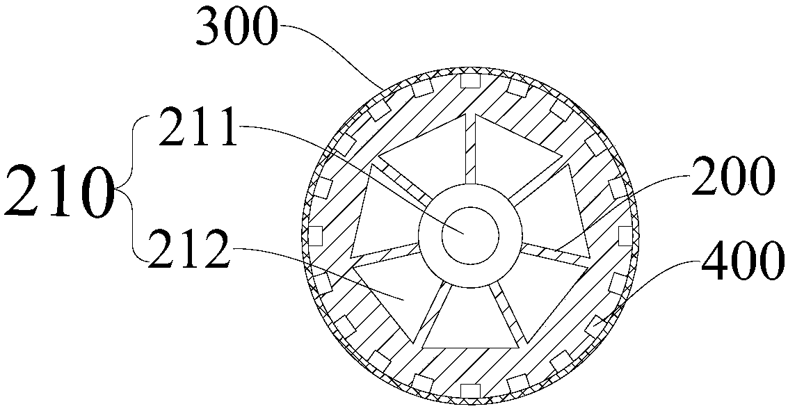
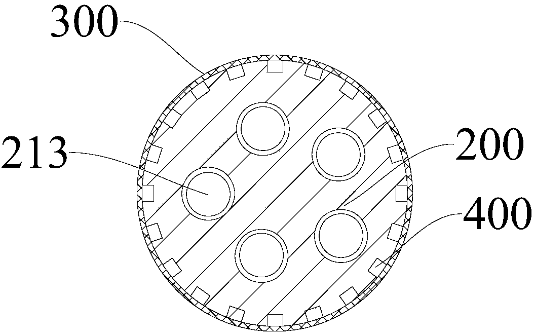
Image


Examples
Embodiment 1
[0044] In this embodiment, the side wall on the opposite side of the smelting furnace adopts the side blowing lance of the embodiment of the present invention, and the side blowing lances are arranged in pairs, and the smelting furnace is used to smelt the copper concentrate, and the copper concentrate includes ( Mass percentage components): Cu35%, Fe4.5%, S22%, Ni1%, etc., the specific method is as follows:
[0045] 1000kg of copper concentrate is added into the furnace body from the feeding port, oxygen-rich gas (oxygen content is 95wt%) is introduced from the gas passage in the oxygen lance, and the cooling water is introduced from the water cooling passage, and the clamp between the oxygen lance and the normal line of the furnace wall is adjusted. The angle is 10°, the gas is accelerated in the gas channel, and is dispersed into multiple rotating jets by the shunt cover with an inclined angle at the exit of the gun. There are irregularities in the direction of the molten p...
Embodiment 2
[0048] In this embodiment, the side-blown smelting furnace of the embodiment of the present invention is used to smelt the copper concentrate, wherein the copper concentrate includes (mass percentage components) Cu28%, Fe27%, S30%, SiO27% and quartz flux (containing SiO 2 95%), etc., the side blowing lance of the smelting furnace is located on the opposite side wall of the furnace body, and the angle between the side blowing lance body and the normal direction of the furnace wall surface is 15°, and the outlet velocity direction of the blowing gas is toward the lower part of the molten pool Flow, this kind of injection method partly weakens the velocity component in the horizontal direction, and on the other hand increases the flow path of the gas in the vertical direction, so that the oxygen can fully contact the melt, the oxidation reaction is more thorough, and the heat released is more. , basically meet the needs of self-heating smelting. At the same time, the speed of ga...
PUM
 Abstract
Description
Claims
Application Information
 - Generate Ideas
- Intellectual Property
- Life Sciences
- Materials
- Tech Scout
- Unparalleled Data Quality
- Higher Quality Content
- 60% Fewer Hallucinations
Browse by: Latest US Patents, China's latest patents, Technical Efficacy Thesaurus, Application Domain, Technology Topic, Popular Technical Reports.
© 2025 PatSnap. All rights reserved.Legal|Privacy policy|Modern Slavery Act Transparency Statement|Sitemap|About US| Contact US: help@patsnap.com