
Pulse forming network based on cathode short-circuit grid-controlled thyristor

A technology of thyristor and cathode, applied in the electronic field, can solve the problems of poor di/dt capability of thyristor, complex drive and protection, large power consumption of device conduction, etc., and achieve the effect of wide application field, low power consumption and simple drive control

Inactive Publication Date: 2018-06-29
UNIV OF ELECTRONICS SCI & TECH OF CHINA
View PDF4 Cites 5 Cited by
  • Summary
  • Abstract
  • Description
  • Claims
  • Application Information

AI Technical Summary

Problems solved by technology

However, due to the current concentration effect during the turn-on process, the di / dt capability of the thyristor is poor
In addition, thyristors are flow-controlled devices, and their drive and protection are more complicated than voltage-controlled devices
IGBT is mainly used in high-frequency medium pulse power supply. IGBT is a voltage-controlled device, and the drive is relatively simple. However, the degree of conductance modulation of IGBT is limited by the drift region and the reverse-biased PN junction of the P-type base region, resulting in the conduction power consumption of the device. Larger; in addition, the conduction of the IGBT is controlled by the gate voltage, and the maximum current is also limited by the saturation current
Gate Controlled Thyristor ( M OS- C onrolled T hyristor, MCT) has low-resistance characteristics similar to thyristors, and has high di / dt capability and voltage control characteristics, but the device needs gate control signals of different signs during the switching process, resulting in more complex drive circuits (Temple V A K.MOS controlledthyristors (MCT's)[C].Electron Devices Meeting,1984International.IEEE,1984:282-285.)

Method used


Image

  • Pulse forming network based on cathode short-circuit grid-controlled thyristor
  • Pulse forming network based on cathode short-circuit grid-controlled thyristor
  • Pulse forming network based on cathode short-circuit grid-controlled thyristor

Examples


Embodiment Construction

[0024] Below in conjunction with specific accompanying drawing, the present invention is described in further detail:

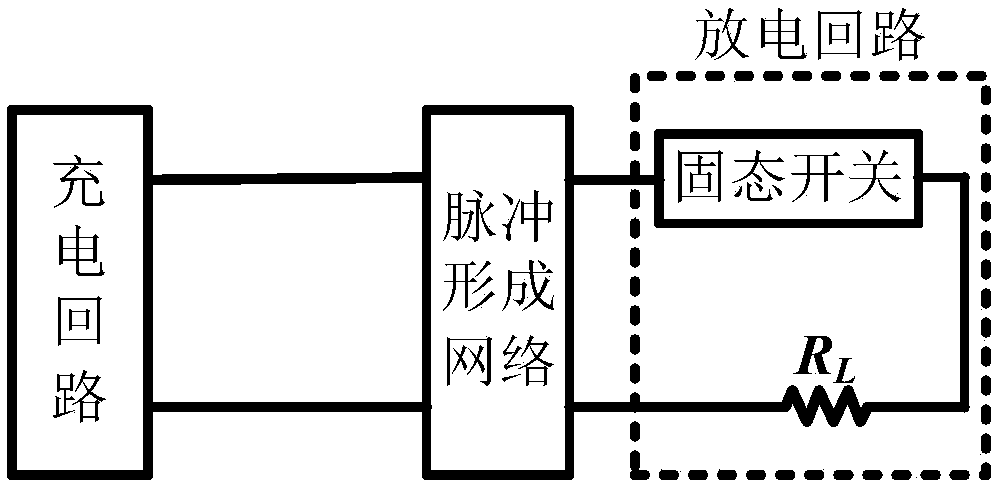
[0025] Such as figure 1 As shown, the entire pulse network forming system includes a charging circuit, a pulse forming network, and a discharging circuit.

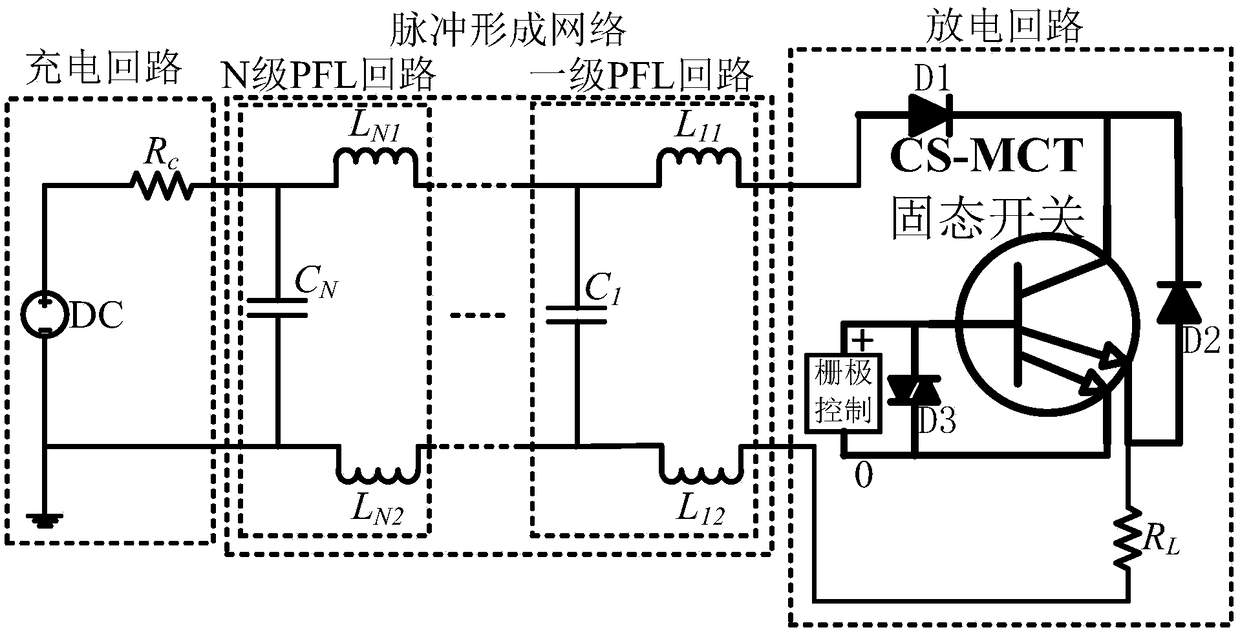
[0026] PFN (Pulse Forming Network) is composed of several sets of capacitance and inductance arrays. The most commonly used in engineering is the inductance type PFN such as equal capacitance as an example. Because the equal-capacitance and other inductance PFN has the characteristics of simple structure and convenient implementation, and is very similar to the distribution parameters of the transmission line. The equal-capacitance and equal-inductance PFN divides the PFL (pulse transmission line) into N segments of equal length and interconnection. In engineering, an ideal transmission line without loss is used, so the equivalent circuit diagram of each segment of PFL is as follows figure 2 Shown in t...


PUM


Abstract

The invention belongs to the field of the power electronics, and specifically a pulse forming network based on a cathode short-circuit grid-controlled thyristor (CS-MCT). The pulse forming network mainly comprises a charging loop composed of a DC power supply and a charging resistor, N-step pulse forming network part, a discharging loop composed of a one-way conducting diode, a CS-MCT, a freewheeldiode, a two-way clamping diode and a load, and a device grid control part, wherein the CS-MCT adopts the four-end connection, and a grid cathode (kevin cathode) is added in comparison with the normal three-end device. The pulse forming network disclosed by the invention has the advantages that the influence on the grid cathode loop by instantaneous high voltage induced by a cathode inductor canbe effectively inhibited, and the breakdown invalid of the grid caused by the overvoltage is avoided; the grid only has the effect of triggering the conduction, when a device enters a thyristor work mode after the latch is conducted, the electric-conducting modulation effect is further reinforced, the conductivity is free from the control of the grid and the limitation of the saturation current, and the greater pulse current can be realized under small area.

Description

technical field [0001] The invention belongs to the field of electronic technology, and in particular relates to a pulse forming network based on cathode short-circuit gate-controlled thyristors. Background technique [0002] Pulse power technology is a new science and technology developed in the early 1960s due to the needs of national defense research. Simply put, pulse power technology is an electrophysical technology that quickly compresses the energy stored slowly and releases it to the load in the form of pulses. With the development of nuclear physics, electron beam accelerator physics, laser and plasma physics research, pulse power technology has developed rapidly and has become one of the most active cutting-edge technologies in the world. It has broad application prospects in both military and civilian fields. , The military field is used in nuclear fusion technology, national defense and military defense, etc.; the civilian field is used in food processing, medic...

Claims


Application Information

Patent Timeline
IPC IPC(8): H03K3/57
CPCH03K3/57
Inventor 陈万军左慧玲刘超陶宏李青岭
Owner UNIV OF ELECTRONICS SCI & TECH OF CHINA
Learn More