
Coil for electromagnetic pump

A technology of electromagnetic pumps and coils, applied in the direction of coils, parts of pumping devices for elastic fluids, pumps, etc., can solve problems such as complexity, expensive model manufacturing and distribution, reduce quantity, reduce heat dissipation, avoid or The effect of reducing heat dissipation

Active Publication Date: 2018-06-29
GOTEC
View PDF7 Cites 2 Cited by
  • Summary
  • Abstract
  • Description
  • Claims
  • Application Information

AI Technical Summary

Problems solved by technology

Manufacture and distribution of equally important multiple models is expensive and complex

Method used


Image

  • Coil for electromagnetic pump
  • Coil for electromagnetic pump
  • Coil for electromagnetic pump

Examples


Embodiment Construction

[0092] Figure 6 A wire 20 is shown wound around a hollow cylindrical support 21 made of insulating plastic material. This element is used for overmolding to serve as a winding in the coil described below.

[0093] Figure 7 shown with Figure 6 The same element as in , but covered with an overmolding 4 that completely surrounds the wires to protect them and prevent leakage risks. Even though the cross-section of the overmolded portion of the wire is substantially circular, the cross-section of the overmold 4 in a plane transverse to the longitudinal axis a of the coil substantially corresponds to a square with rounded corners. The cladding edge is equipped with radial cooling fins 40 . The fins are longer in at least two corners 41 than in the middle of the edge 41 in order to utilize the available volume between the corners of the square and the conductor volume.

[0094] A first groove 43 is provided to allow a removable thermal fuse or thermal switch to protect the co...


PUM


Abstract

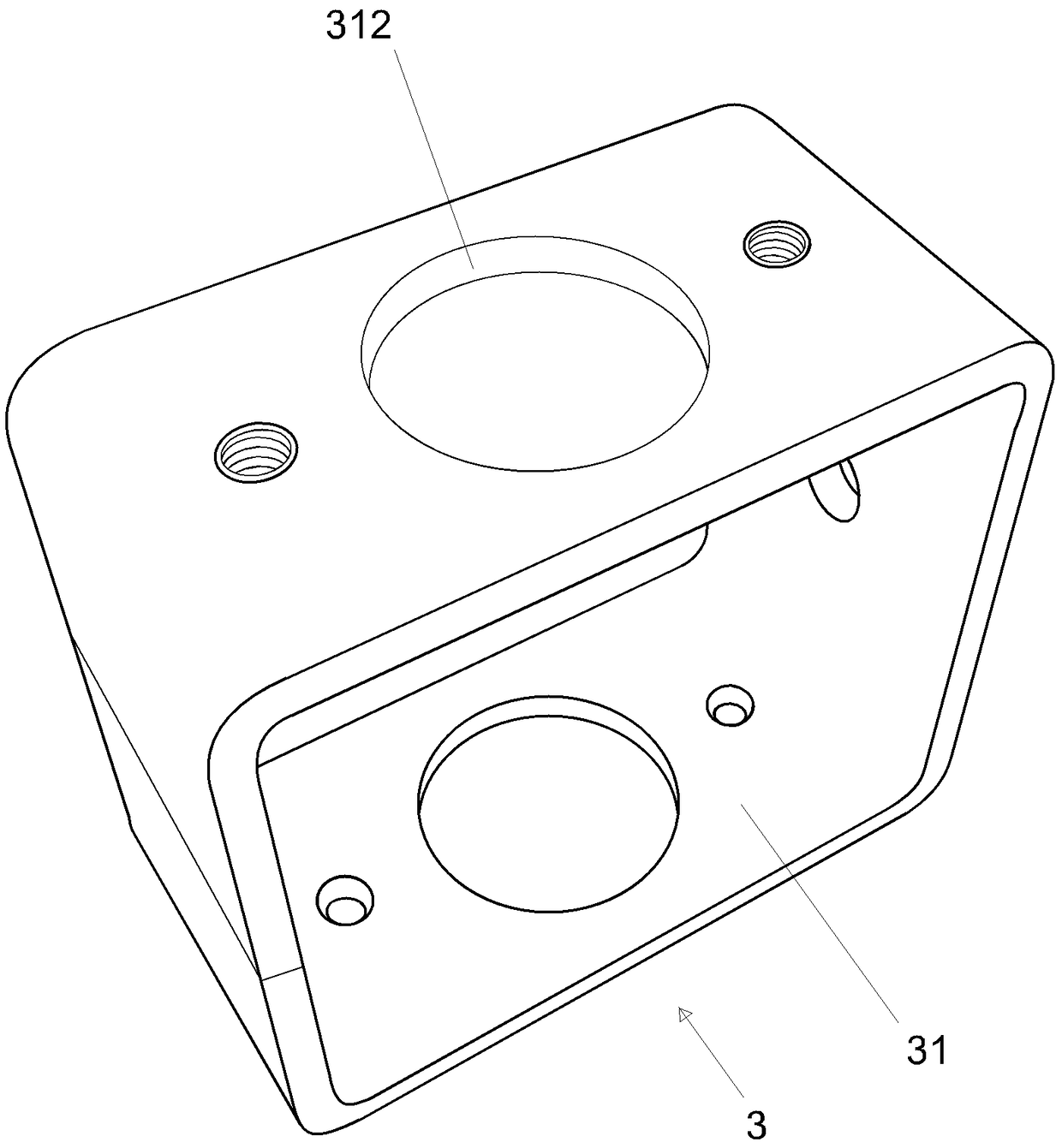
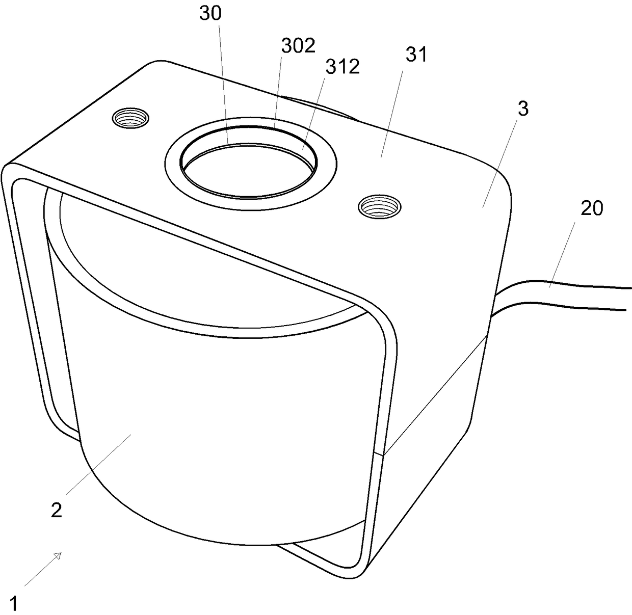
A coil (1) for an electromagnetic pump is disclosed, comprising a winding (2) constituted by a conductive wire wound around a hollow cylindrical support (21); a frame (3) of ferromagnetic material comprising on the one hand a core (30) provided with a cylindrical opening and passing through said winding, and on the other hand a loop (31) around the winding (2) to close the magnetic circuit betweenthe two ends of this nucleus; an overmoulding (4) of synthetic material around the winding, of which an outer surface forms radial cooling fins (40).

Description

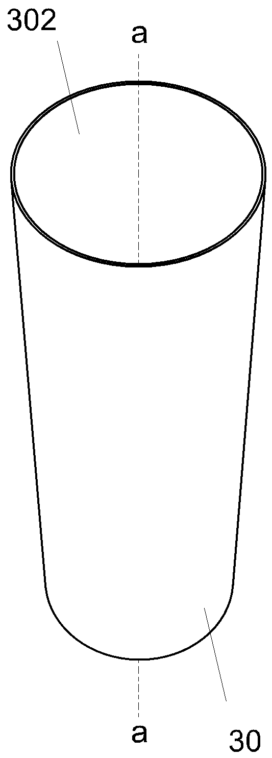
technical field [0001] The invention relates to the field of electromagnetic pumps and coils for electromagnetic pumps. Background technique [0002] An example of a solenoid pump 5 is shown in the Figure 10 middle. Typically, the pump shown comprises a fluid supply conduit 6 upstream of the pump, a fluid output conduit 7 downstream of the pump, and a movable piston 8 between the two conduits. The electromagnetic coil 2 forms a magnetic field that displaces the piston 8 in the cylinder 302 against the action of the spring 9 to generate a pumping motion. Examples of such pumps are described, for example, in patent applications WO2013152975 and WO2014177442 filed in the applicant's name. [0003] A first type of coil 1 used in the prior art for electromagnetic pumps is shown in Figure 1 to Figure 3 middle. The shown coil comprises a winding 2 formed by wire wound around a hollow cylindrical support and the outer surface of the winding is protected by varnish or insulatin...

Claims


Application Information

Patent Timeline
Patent Type & Authority Applications(China)
IPC IPC(8): H01F5/02H01F3/10H01F41/098H01F41/00F04B17/04
CPCF04B17/04H01F3/10H01F5/02H01F41/00H01F41/098F04B17/046F04B53/129F04B53/16H01F7/081H01F2007/083
Inventor V.南彻恩F.达耶
Owner GOTEC
Learn More