
Shielding shell for a connector

A technology for shielding shells and connectors, which is applied to the protective grounding/shielding devices of connecting parts, parts of connecting devices, and connections, to achieve the effect of improving shielding efficiency and optimizing the use of space

Inactive Publication Date: 2012-04-18
FCI ASIA PTE LTD
View PDF2 Cites 1 Cited by
  • Summary
  • Abstract
  • Description
  • Claims
  • Application Information

AI Technical Summary

Problems solved by technology

However, folding techniques can often provide limited accuracy, which can require significant effort and expense to meet manufacturing tolerances and provide adequate shielding

Method used


Image

  • Shielding shell for a connector
  • Shielding shell for a connector
  • Shielding shell for a connector

Examples


Embodiment Construction

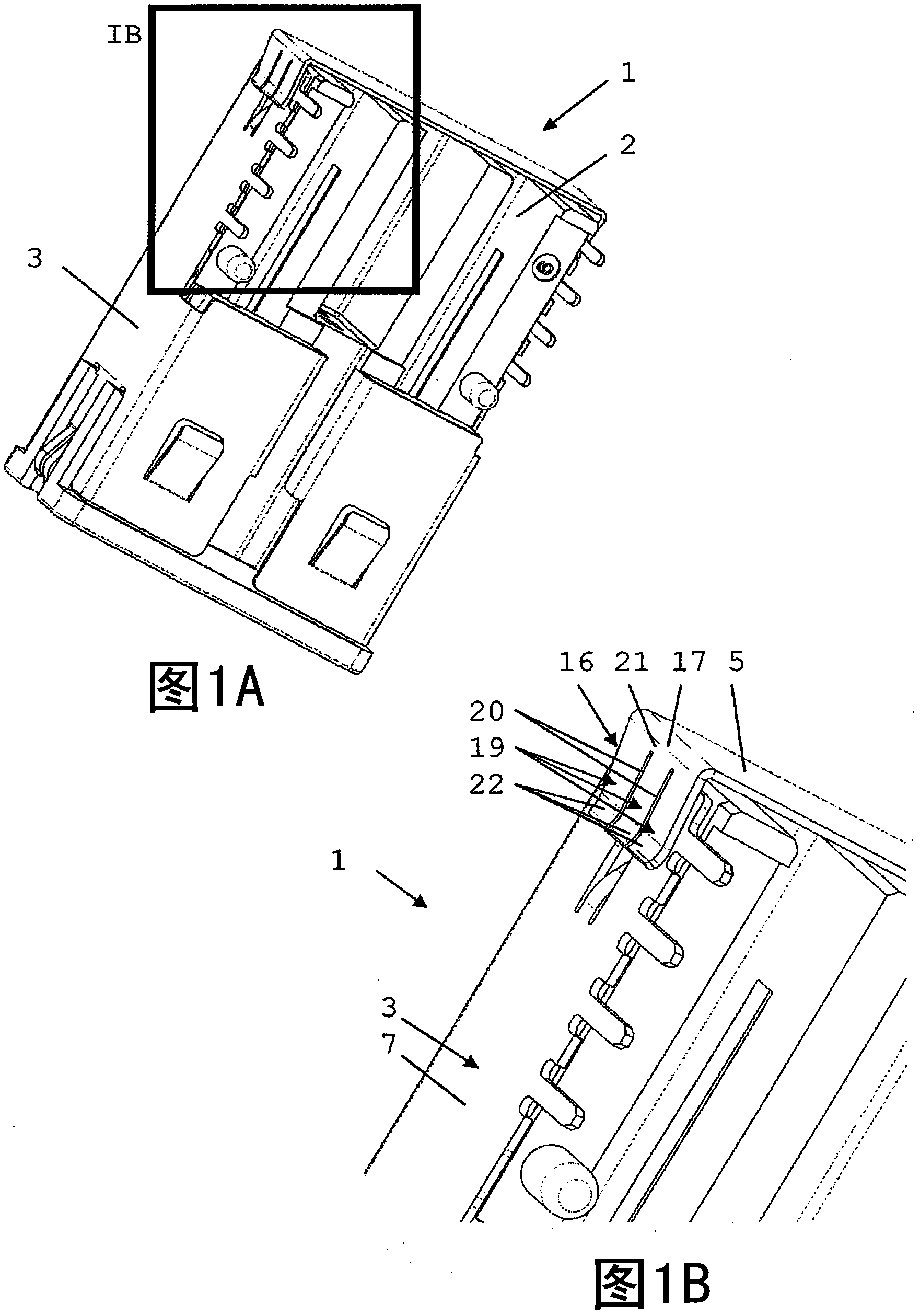
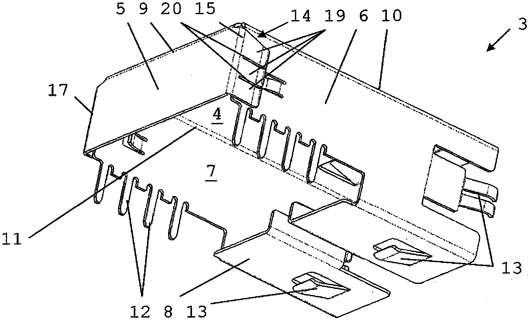
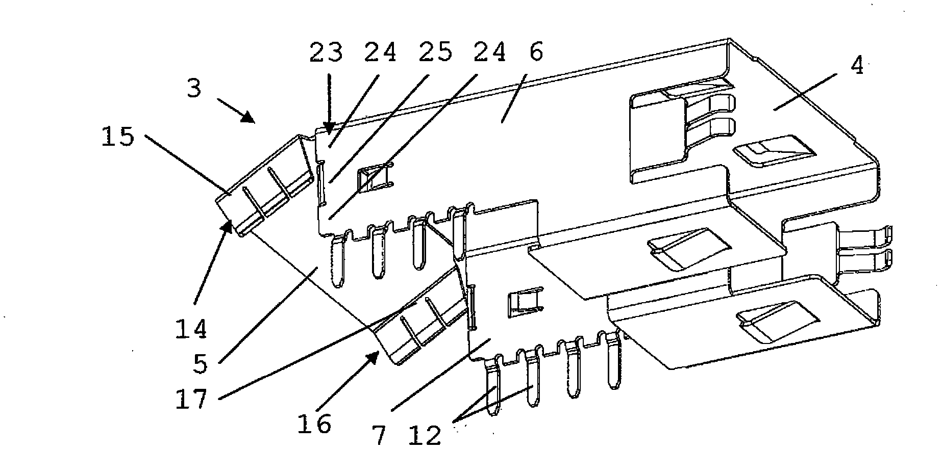
[0020] Figure 1A and 1B A connector 1 comprising a connector body 2 and a shielding shell 3 is shown. shielding case 3 in figure 2 is shown in . Figures 3A-3E The shielding case shown is generally similar to the Figure 1A-2 shielding shell. In the drawings and in the discussion that follows, like features are indicated by like reference numerals.

[0021] The illustrated connector 1 is a right angle connector configured for mounting to another object, in particular a circuit board (not shown). The shielding case 3 includes a first wall 4 on its top side, a second wall 5 on its rear side, a third wall 6 and a fourth wall 7 on substantially opposite sides, respectively, and on its bottom side A further wall portion 8 is included. The shielding housing 3 is mounted to the connector body 2 mainly by the interaction between the wall portion 8 and other portions protruding from the wall portion 8 which are received in the in the connector body 2. Thereby, the connector b...


PUM


Abstract

A Shielding shell (3) for a connector is disclosed which comprises a first wall (4), a second wall (5) and a third wall (6). The first wall, the second wall and the third wall are arranged mutually at an angle to each other. At least the first wall and the second wall are connected to each other by a first folded edge. The shielding shell further comprises a first contact portion (14) connected with the second wall by a second folded edge (16), the first contact portion being arranged substantially parallel to the third wall and comprising a plurality of contact segments contacting said third wall.

Description

technical field [0001] The present disclosure relates to the field of connectors, in particular to the field of shielding structures for connectors, and more particularly to the field of shielding shells for connectors. Background technique [0002] Connectors used to connect one or more signals may need to be shielded against electromagnetic noise generated or received by the carrier along which the signals travel. Such shielding may be effectively provided in the form of a shielding can comprising an electrically conductive material covering at least a portion of the connector. [0003] When designing and manufacturing such shielded housings and connectors including such housings, a balance must be found between shielding efficiency, material consumption, and ease of manufacture. Manufacturing the shield by folding a sheet of material, such as a metal sheet, around (a part of) the connector terminal housing has proven to be a useful technique for providing a shielded hous...

Claims


Application Information

Patent Timeline
Patent Type & Authority Applications(China)
IPC IPC(8): H01R13/6581H01R13/658
CPCH01R12/707H01R13/658H01R23/7063H01R43/16H01R13/6583
Inventor P·波特N·范斯蒂普特T·卡斯马克斯
Owner FCI ASIA PTE LTD
Learn More