Solar heat collection device facing seasonal frost area roadbed construction, and implementation method
A technology for solar heat collection and permafrost areas, which is applied in the field of roadbed disease prevention and control in permafrost areas, can solve the problems of poor heat supply control effect, poor effect of anti-frost heave technology, and high maintenance costs of the roadbed, and achieves compact structure, flexible layout, small footprint effect
- Summary
- Abstract
- Description
- Claims
- Application Information
AI Technical Summary
Problems solved by technology
Method used
Image
Examples
Embodiment 1
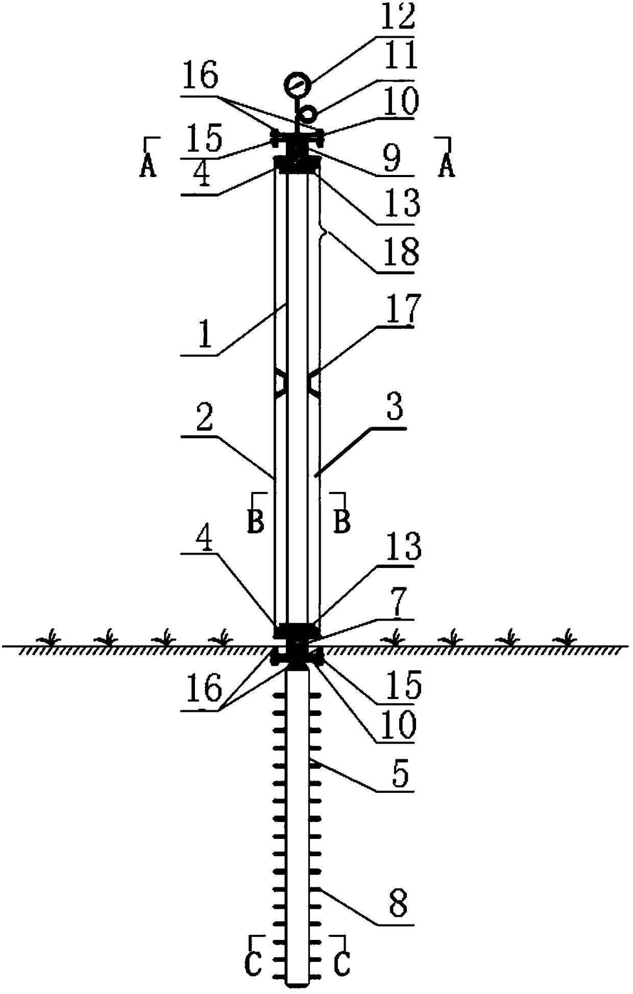
[0046] Embodiment 1 of the present invention provides a solar heat collection device for preventing roadbed frost heave in seasonally frozen soil areas, the device includes a ground heat collection unit and a roadbed heating unit, and the ground heat collection unit is used to convert solar energy heat energy, and transfer the heat energy to the roadbed heating unit; the roadbed heating unit is used to transfer the heat energy transferred by the above-ground heat collection unit to the frozen soil roadbed.
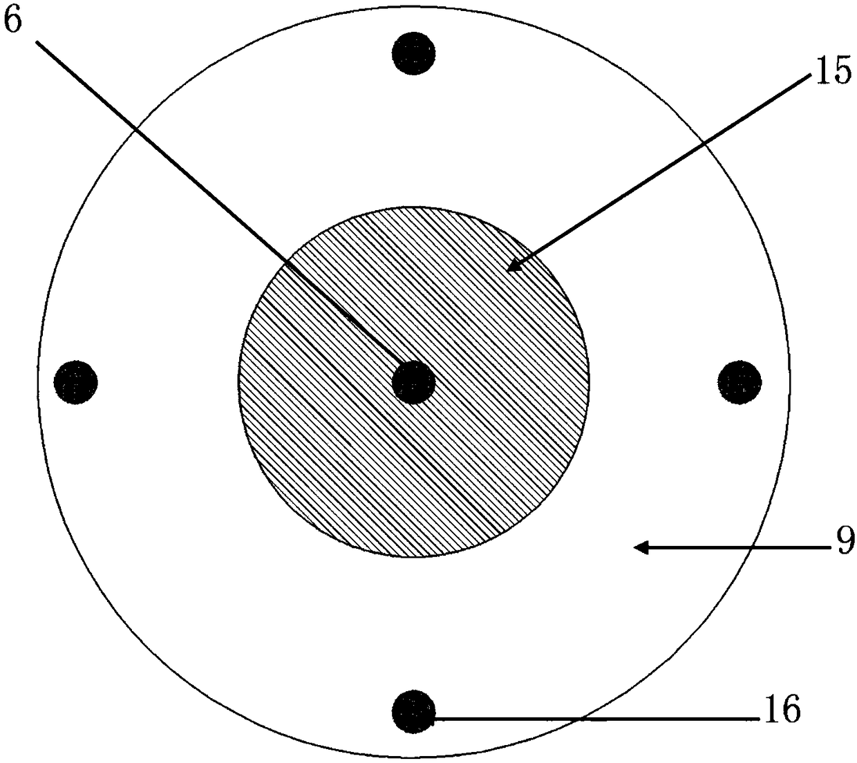
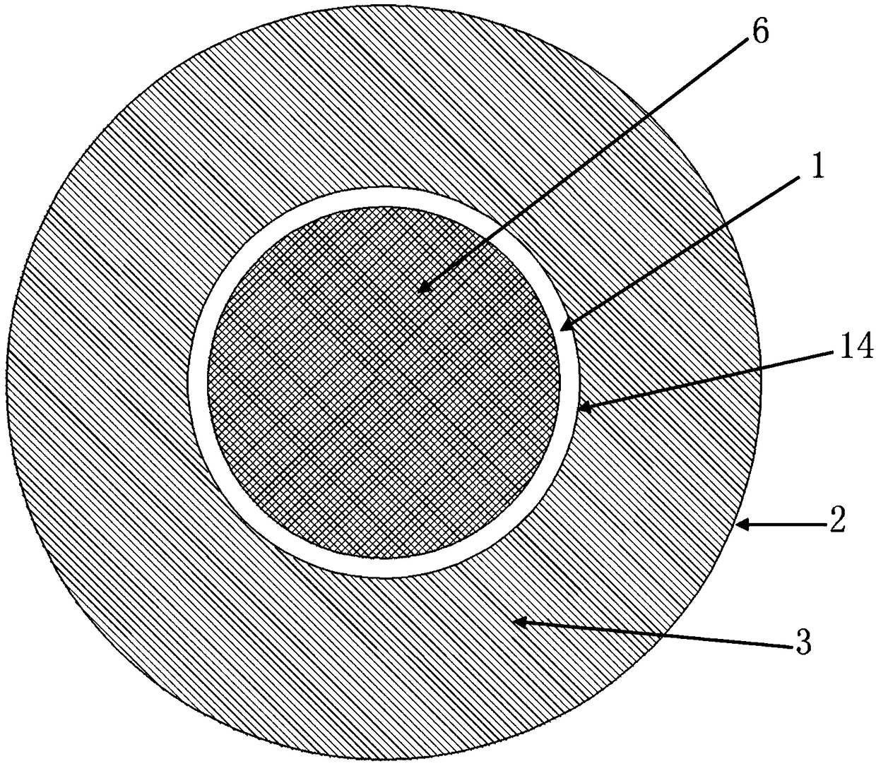
[0047] Such as figure 1 As shown, it is a structural diagram of a solar heat collection device for subgrade engineering in seasonally frozen soil regions according to an embodiment of the present invention. The above-ground heat collection unit includes a heat absorption pipe 1, and the heat absorption pipe 1 is made of a metal material. , high heat collection temperature, good thermal conductivity and processing performance, and corrosion resistance; the outer sleeve of t...
Embodiment 2
[0056] Embodiment 2 of the present invention provides a manufacturing and assembling method of a solar heat collecting device for subgrade engineering in seasonal frozen soil regions. In this embodiment, the specific manufacturing steps of the ground heat collecting unit include:
[0057] (a) Select a stainless steel tube of a certain length, sputter the solar energy selective absorption coating on the outer wall of the stainless steel tube, and leave a 5cm blank at both ends of the stainless steel tube, which is a metal heat absorbing tube;
[0058] (b) Choose a glass tube with a length difference of 10cm from the metal heat absorbing tube, and use a glass-metal sealing joint to seal the metal heat absorbing tube and the glass tube. - the outer side of the metal seal joint;
[0059] (c) evacuate the interlayer space between the metal heat-absorbing tube and the glass tube through the vacuum tail nozzle 18 to obtain a heat-insulating cavity;
[0060] (d) Weld threaded flanges...
Embodiment 3
[0071] Embodiment 3 of the present invention provides the implementation method of the solar heat collecting device facing the subgrade engineering in the seasonally frozen soil area, such as Figure 5 As shown, it is a flow chart of the implementation method of the solar heat collection device for roadbed engineering in the seasonally frozen soil area described in Embodiment 3 of the present invention. The implementation method includes the following steps:
[0072] Step S110: Determine the frost heave depth range of the seasonally frozen soil layer under the subgrade; in winter, determine the frost heave depth range of the seasonally frozen soil by laying out temperature measuring holes and deformation monitoring holes in combination with geological radar exploration;
[0073] Step S120: measure the thermophysical parameters and thermal load of the seasonally frozen ground layer; determine the thermally physical property parameters of the stratum through the thermal response ...
PUM
 Abstract
Description
Claims
Application Information
 - R&D Engineer
- R&D Manager
- IP Professional
- Industry Leading Data Capabilities
- Powerful AI technology
- Patent DNA Extraction
Browse by: Latest US Patents, China's latest patents, Technical Efficacy Thesaurus, Application Domain, Technology Topic, Popular Technical Reports.
© 2024 PatSnap. All rights reserved.Legal|Privacy policy|Modern Slavery Act Transparency Statement|Sitemap|About US| Contact US: help@patsnap.com


