Manufacturing method of high-efficiency low-noise piston compressor valve plate
A manufacturing method and piston-type technology, which is applied in the direction of liquid variable displacement machinery, mechanical equipment, variable displacement pump components, etc., can solve the problems of increased pressure loss, large valve displacement, high suction speed, etc., and achieve pressure loss The effect of reducing and reducing the noise of the valve plate and improving the energy efficiency ratio
- Summary
- Abstract
- Description
- Claims
- Application Information
AI Technical Summary
Problems solved by technology
Method used
Image
Examples
Embodiment 1
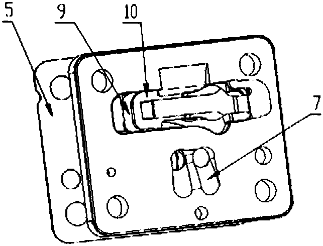
[0039] Embodiment one, such as image 3 Shown:
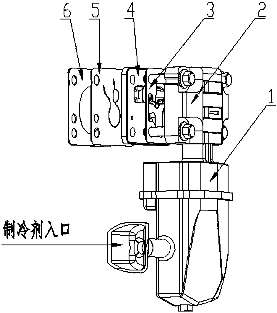
[0040] In the high-efficiency and low-noise piston compressor of the present invention, the valve plate 4 is provided with double suction ports 7, and the double suction ports 7 are composed of two circular through holes.
[0041] The increased area of the suction port of the valve plate of the valve plate of the present invention overcomes the shortcomings of the prior art and can ensure long-term high-efficiency and low-noise operation of the compressor. Due to the fixed speed and displacement of the compressor, its suction capacity remains unchanged. When the area of the suction port of the valve plate increases, the suction speed decreases, the speed of the refrigerant gas flowing through the valve gap decreases, the Mach number decreases, and the pressure The loss is reduced and the energy efficiency ratio of the compressor is improved. At the same time, after the area of the air inlet increases, the mass flow rate ...
Embodiment 2
[0051] Embodiment two, such as Image 6 Shown:
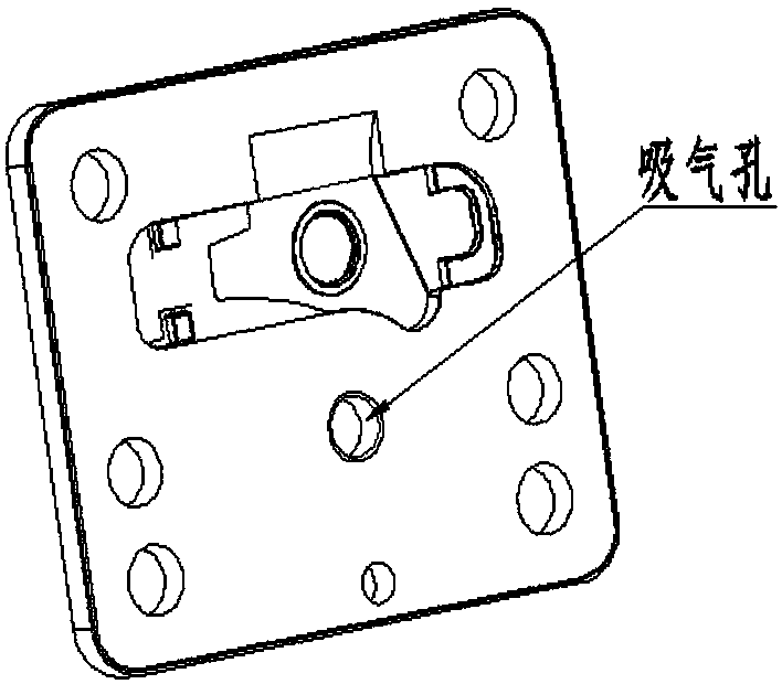
[0052] In the second high-efficiency and low-noise piston compressor of the present invention, the valve plate 4 is provided with a crescent-shaped suction port 12, and the crescent-shaped suction port 12 is a crescent-shaped through hole. The crescent shape is provided with an arc-shaped protrusion facing the opposite side of the groove of the valve plate. At the position of the crescent-shaped protrusion, there is provided a crescent-shaped air suction opening slope 11 , and the crescent-shaped air suction opening slope 11 is from shallow to deep, and the deepest part is connected with the two crescent-shaped air suction openings 12 .
[0053] The valve plate suction hole is a crescent-shaped suction port 12 with a slope, and the area of the crescent-shaped through hole is not increased compared with the prior art; The slope is connected with the crescent-shaped through hole to further increase the area of the suction ho...
Embodiment 3
[0058] Embodiment three, such as Figure 7 Shown:
[0059] Another high-efficiency and low-noise piston compressor of the present invention, wherein the valve plate 4 is provided with a crescent-shaped suction port 12, and the crescent-shaped suction port 12 is a crescent-shaped through hole. Its area is larger than that of the suction port in the prior art.
[0060] The crescent-shaped suction port 12 is connected with the upper muffler chamber of the suction muffler 1 .
[0061] On the side of the valve plate 4 opposite to the groove of the valve plate, the end of the crescent-shaped suction port 12 is provided with a crescent-shaped suction port sealing valve line. The line is level with the surface of the valve plate 4, or 0.01-0.02mm higher than the surface of the valve plate 4.
[0062] The sealing valve line of the crescent-shaped suction port corresponds to the suction valve plate 5, and the reed of the suction valve plate 5 corresponds to the sealing valve line of ...
PUM
 Abstract
Description
Claims
Application Information
 - R&D
- Intellectual Property
- Life Sciences
- Materials
- Tech Scout
- Unparalleled Data Quality
- Higher Quality Content
- 60% Fewer Hallucinations
Browse by: Latest US Patents, China's latest patents, Technical Efficacy Thesaurus, Application Domain, Technology Topic, Popular Technical Reports.
© 2025 PatSnap. All rights reserved.Legal|Privacy policy|Modern Slavery Act Transparency Statement|Sitemap|About US| Contact US: help@patsnap.com


