Explosion-proof frequency converter cooling system and method

An explosion-proof frequency converter and cooling system technology, which is applied in the direction of cooling/ventilation/heating transformation, output power conversion device, electrical components, etc. Limited problems, to achieve the effect of improving explosion-proof performance, best cooling effect, and good electrical insulation performance

Pending Publication Date: 2018-06-19
TIANJIN EMAGING TECH +1
View PDF6 Cites 3 Cited by
  • Summary
  • Abstract
  • Description
  • Claims
  • Application Information

AI Technical Summary

Problems solved by technology

However, this kind of heat dissipation method is generally large in size, and the heat dissipation fins are easy to absorb dust, resulting in a decrease in heat dissipation performance; and the heat dissipation power of the heat pipe is limited, and the heat dissipation effect is not ideal when the power density of the inverter is high.

Method used


Image

  • Explosion-proof frequency converter cooling system and method
  • Explosion-proof frequency converter cooling system and method
  • Explosion-proof frequency converter cooling system and method

Examples


Embodiment 1

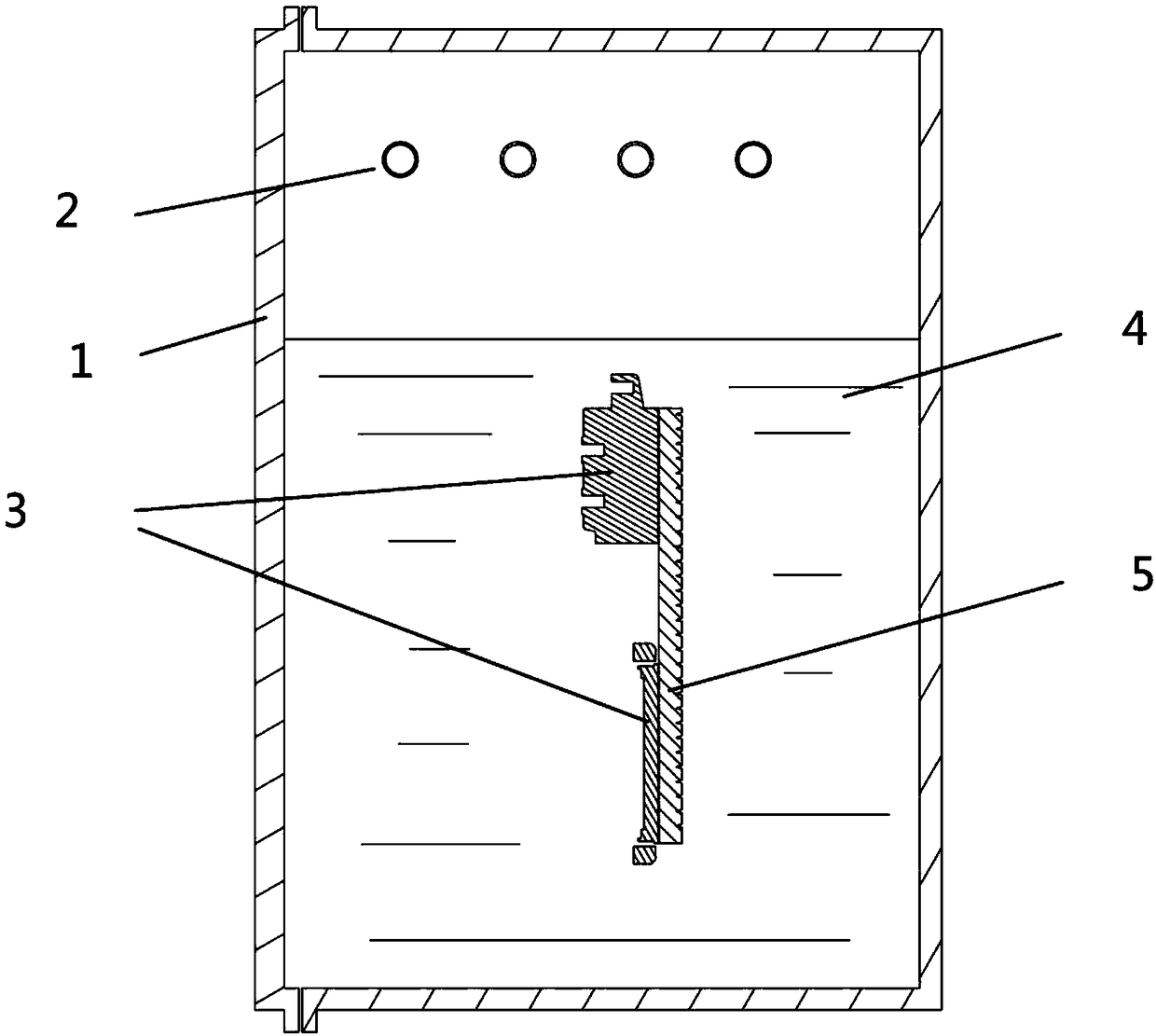
[0035] Such as figure 1 As shown, an explosion-proof inverter cooling system includes a housing 1, a condensation pipe 2 and a heat dissipation pipe.

[0036] A high-power device 3 of an explosion-proof frequency converter is arranged inside the housing 1 to protect and support the high-power device 3 . The casing 1 is equipped with a cooling liquid 4 , and the high-power device 3 is immersed in the cooling liquid 4 . The cooling liquid 4 can electrically insulate the high-power device 3 .

[0037] The heat dissipation plate 5 is arranged in the housing 1 and immersed in the cooling liquid 4 ; the high-power device 3 is arranged on the heat dissipation plate 5 . A large amount of heat generated by the high-power device 3 during operation is transferred to the cooling plate 5, and the temperature of the cooling plate 5 rises;

[0038] Condenser pipe 2 comprises body, inlet end and outlet end, and body is arranged in housing 1, and is positioned at the top of cooling liquid 4...

Embodiment 2

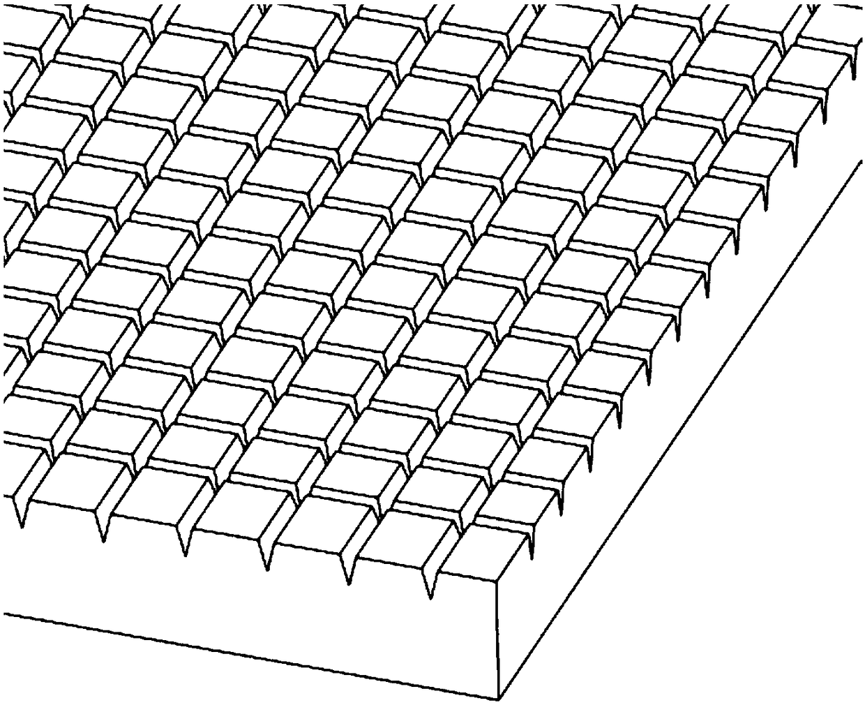
[0045] As shown in Embodiment 1, the only difference is that the surface of the radiator is provided with an enhanced boiling structure.

[0046] Such as figure 2 As shown, there are several protrusions on the enhanced boiling structure, and the protrusions increase the contact area between the cooling liquid 4 and the enhanced boiling structure, which can accelerate the heat transfer speed.

Embodiment 3

[0048] As shown in Embodiment 2, the only difference is that the condensation pipe 2 is a smooth-walled copper pipe.

[0049] The smooth-walled copper tube has a high thermal conductivity, which can quickly absorb the heat released when the steam condenses, and quickly transfer the heat to the cooling medium in the condensation pipe 2, and the cooling medium transports the heat to the explosion-proof frequency converter.


PUM


Abstract

The invention relates to a cooling system and method, and particularly relates to an explosion-proof frequency converter cooling system and method. The system comprises a shell, a heat radiation plateand condensation pipes. The shell is internally filled with cooling liquid. The heat radiation plate is arranged in the shell and immersed in the cooling liquid. The high-power devices of the explosion-proof frequency converter are arranged on the heat radiation plate. The bodies of the condensation pipes are arranged in the shell and positioned above the cooling liquid. The inlet end and the outlet end of the condensation pipes are arranged outside the shell. The cooling medium is piped into the condensation pipes. The high-power devices of the explosion-proof frequency converter are immersed by the cooling liquid so that the explosion-proof performance of the explosion-proof frequency converter can be greatly enhanced; the whole system has no risk of water leakage so that the safety performance of the explosion-proof frequency converter can be increased; and the heat is transferred through the cooling liquid and the cooling liquid is condensed and recycled through the condensation pipes so as to have excellent explosion-proof frequency converter cooling effect.

Description

technical field [0001] The invention relates to a cooling system and method, in particular to an explosion-proof inverter cooling system and method. Background technique [0002] During the operation of the explosion-proof inverter, the high-power devices of the explosion-proof inverter will generate a lot of heat. If the heat is not discharged in time, it will affect the performance of the high-power device, and even affect the life of the high-power device. At present, the cooling methods commonly used in explosion-proof inverters include water cooling and heat pipe cooling. [0003] When the heat is dissipated by water cooling, the high-power components of the explosion-proof inverter are fixed on the water-cooling plate, and cooling water is passed into the inside of the water-cooling plate for cooling. Because the water inlet and the water outlet of the water cooling plate are connected with the water pipe joint, there is a hidden danger of water leakage. In addition,...

Claims


Application Information

Patent Timeline
Patent Type & Authority Applications(China)
IPC IPC(8): H02M1/00H05K7/20
CPCH02M1/00H05K7/20936
Inventor 邓仁杰毕刘新魏庆施黄璋衣富成杨亲成朱俊康绍峰徐刚彭爱国
Owner TIANJIN EMAGING TECH
Why Eureka
Try Eureka