Hinge electric resistance welding process

A resistance welding and resistance welding machine technology, applied in resistance welding equipment, welding equipment, manufacturing tools, etc., can solve problems such as low work efficiency, strong environmental damage, and environmental pollution

Active Publication Date: 2018-06-15
HERON INTELLIGENT EQUIP CO LTD
View PDF5 Cites 3 Cited by
  • Summary
  • Abstract
  • Description
  • Claims
  • Application Information

AI Technical Summary

Problems solved by technology

[0002] The traditional production method of the hinge is mainly produced by arc welding. It first hollows out the middle part of one side of the iron plate, and then bends the two sides of the hollow into inner holes respectively. Then, it adopts arc welding. The joint between the bent end and the iron plate is welded or cast through a mold; the welded hinge is mainly arc welded, and arc welding is not only low in work efficiency, but also highly destructive to the environment; The page needs to introduce molten metal into the mold cavity, which not only consumes high energy, but also pollutes the environment

Method used


Image

  • Hinge electric resistance welding process
  • Hinge electric resistance welding process
  • Hinge electric resistance welding process

Examples


Embodiment 1

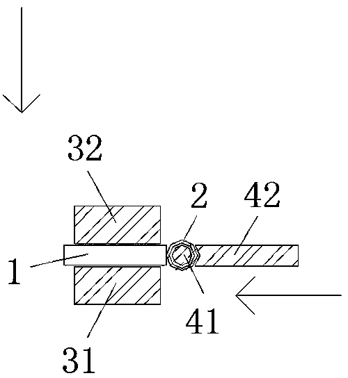
[0023] Example one, reference figure 1 As shown, in the resistance welding process of the hinge of the present invention, the hinge includes a sheet 1 and a shaft sleeve 2 assembled with the sheet 1. The shaft sleeve 2 is cut from a steel pipe, and the shaft sleeve 2 is provided with an inner hole. Sheet 1 is cut from steel strips or steel plates. The hinge is manufactured by welding sheet 1 and sleeve 2 using a resistance welding process. The sheet 1 and sleeve 2 are accurately positioned before passing It is welded by a resistance welding process, which is controlled by a resistance welding welding system. The resistance welding system includes a sleeve positioning tooling system and a sheet positioning fixture system. The sheet positioning fixture system includes a reference electrode 31 and a sheet limiter. The fixed electrode 32, the sleeve positioning tooling system includes the sleeve positioning shaft 41 and the sleeve limiting fixed electrode 42; respectively connected ...

Embodiment 2

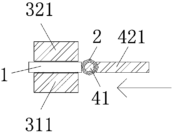
[0025] Example two, reference figure 2 As shown, in the resistance welding process of the hinge of the present invention, the hinge includes a sheet 1 and a shaft sleeve 2 assembled with the sheet 1. The shaft sleeve 2 is cut from a steel pipe, and the shaft sleeve 2 is provided with an inner hole. Sheet 1 is cut from steel strips or steel plates. The hinge is manufactured by welding sheet 1 and sleeve 2 using a resistance welding process. The sheet 1 and sleeve 2 are accurately positioned before passing It is welded by a resistance welding process, which is controlled by a resistance welding welding system. The resistance welding system includes a sleeve positioning tooling system and a sheet positioning fixture system. The sheet positioning fixture system includes a reference electrode 31 and a sheet limiter. The fixed electrode 32, the sleeve positioning tooling system includes the sleeve positioning shaft 41 and the sleeve limiting fixed electrode 42; respectively connected...

Embodiment 3

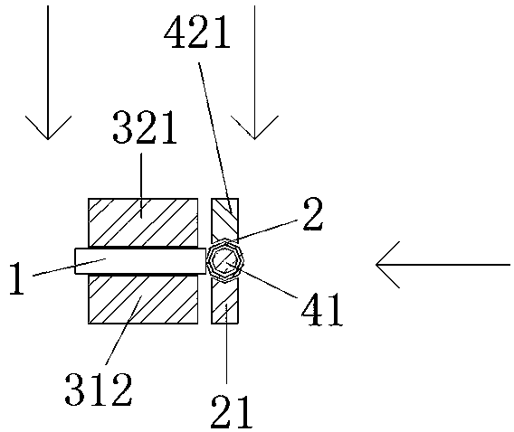
[0030] Example three, reference image 3 As shown, in the resistance welding process of the hinge of the present invention, the hinge includes a sheet 1 and a shaft sleeve 2 assembled with the sheet 1. The shaft sleeve 2 is cut from a steel pipe, and the shaft sleeve 2 is provided with an inner hole. Sheet 1 is cut from steel strips or steel plates. The hinge is manufactured by welding sheet 1 and sleeve 2 using a resistance welding process. The sheet 1 and sleeve 2 are accurately positioned before passing It is welded by the resistance welding process. The resistance welding process is controlled by the resistance welding welding system. The resistance welding system includes a sleeve positioning tooling system and a sheet positioning fixture system. The sheet positioning fixture system includes a sheet reference electrode and a sheet. Limiting fixed electrode 32, the sleeve positioning tooling system includes sleeve positioning shaft 41, sleeve limit fixed electrode 42 and sle...


PUM


Abstract

The invention provides a hinge electric resistance welding process. A hinge comprises a hinge piece and a shaft sleeve which is assembled with the hinge piece, the shaft sleeve is formed by cutting asteel pipe, and the hinge piece is formed by cutting a steel strip or a steel plate. The hinge is manufactured by accurately positioning the hinge piece and the shaft sleeve and then welding the hingepiece and the shaft sleeve through a resistance welding process, and the electric resistance welding process is controlled by an electric resistance welding system. The electric resistance welding system comprises a shaft sleeve positioning tool system and a hinge piece positioning tool system, the hinge piece positioning tool system comprises a reference electrode and a hinge piece limiting andfixing electrode, and the shaft sleeve positioning tool system comprises a shaft sleeve positioning shaft and a shaft sleeve limiting and fixing electrode. According to the hinge electric resistance process, the traditional production process of the hinge is innovated, the production process of the hinge is simplified, the production efficiency of the hinge is high, the production time is short, the use of arc welding is avoided, and the phenomenon that the environment is polluted or the environment is damaged is avoided; and the process is environment-friendly, convenient, rapid and simple touse, low in cost, and uniform and full in welding spots of welding joints.

Description

Technical field [0001] The invention relates to a hinge resistance welding process. Background technique [0002] The traditional production method of hinges is mainly produced by arc welding. Firstly, the middle part of one side of the iron plate is hollowed out, and then the hollowed out two sides are respectively rolled into inner holes, and then arc welding is adopted. The joint between the end of the coil and the iron plate is welded or cast through a mold; the welding hinge is mainly arc welding, which not only has low efficiency, but also has a strong destructive effect on the environment; It is necessary to introduce molten metal into the mold cavity, which not only consumes high energy, but also pollutes the environment. The invention innovates the traditional production technology of the hinge, and makes the production of the hinge not only simpler, but also very environmentally friendly, without pollution to the environment, and low cost. Summary of the invention [0...

Claims


Application Information

Patent Timeline
Patent Type & Authority Applications(China)
IPC IPC(8): B23K11/00
CPCB23K11/002
Inventor 邹春芽
Owner HERON INTELLIGENT EQUIP CO LTD
Why Eureka
Try Eureka