Heat pump air-conditioning system and control method thereof
A heat pump air conditioner and control method technology, applied in the field of air conditioners, can solve the problems of large indoor temperature drop, reduced indoor comfort, etc., and achieve the effects of large evaporation temperature difference, reduction of volume and cost, and slowing down of frost formation.
- Summary
- Abstract
- Description
- Claims
- Application Information
AI Technical Summary
Problems solved by technology
Method used
Image

Examples
Embodiment 1
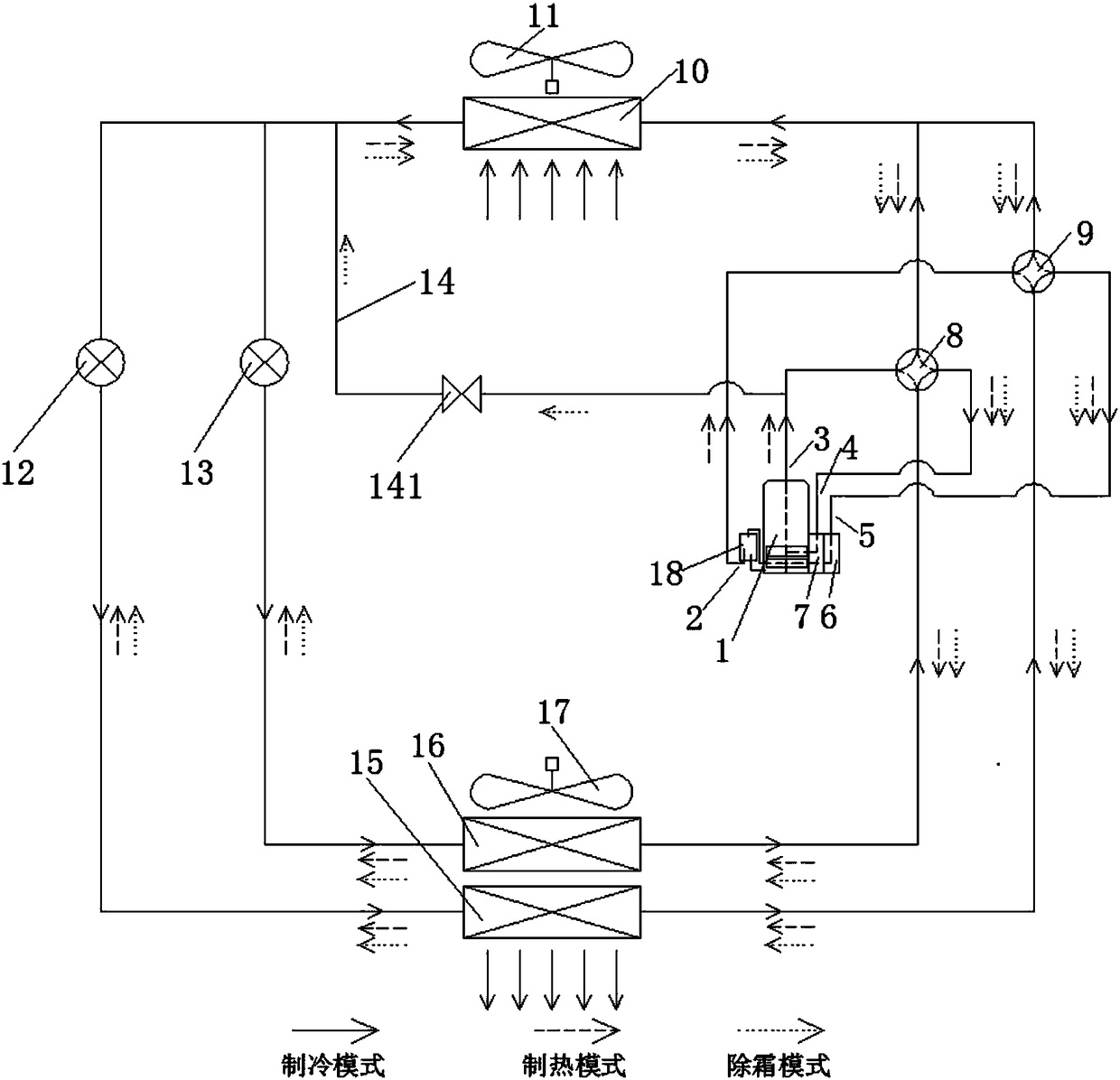
[0041] Such as figure 1 As shown, the at least one indoor heat exchanger includes a first indoor heat exchanger 15 and a second indoor heat exchanger 16, and the first indoor heat exchanger 15 and the second indoor heat exchanger 16 are placed side by side to achieve different The evaporation temperature or the condensation temperature, the different evaporation temperatures can form a cascade cooling of the indoor air, or the different condensation temperatures can form a cascade heating of the indoor air. The at least one outdoor heat exchanger includes a first outdoor heat exchanger 10, the at least one bypass pipeline includes a first bypass pipeline 14, and one end of the first bypass pipeline 14 is connected to the compressor 1, the other end is connected to the first outdoor heat exchanger 10; the first outdoor heat exchanger 10 communicates with the compressor through the first four-way valve 8 and the second four-way valve 9 1 connection; the first bypass line 14 is...
Embodiment 2
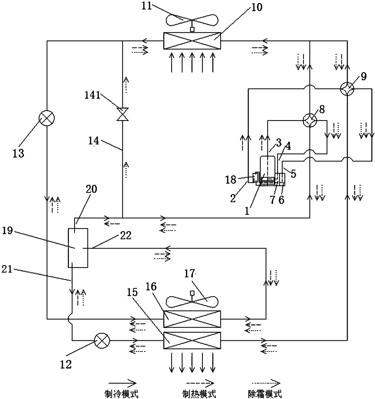
[0046] Such as figure 2 As shown, the at least one indoor heat exchanger includes a first indoor heat exchanger 15 and a second indoor heat exchanger 16, and the first indoor heat exchanger 15 and the second indoor heat exchanger 16 are placed side by side to achieve different The evaporation temperature or the condensation temperature, the different evaporation temperatures can form a cascade cooling of the indoor air, or the different condensation temperatures can form a cascade heating of the indoor air. The at least one outdoor heat exchanger includes a first outdoor heat exchanger 10, the at least one bypass line includes a first bypass line 14, and the first indoor heat exchanger 15 and the second indoor heat exchanger A flasher 19 is arranged between the heat exchangers 16; the flasher 19 is connected to the first four-way valve 8 through the first connecting pipe 20 and then connected to the compressor 1; the flasher 19 is connected to the compressor 1 through the sec...
Embodiment 3
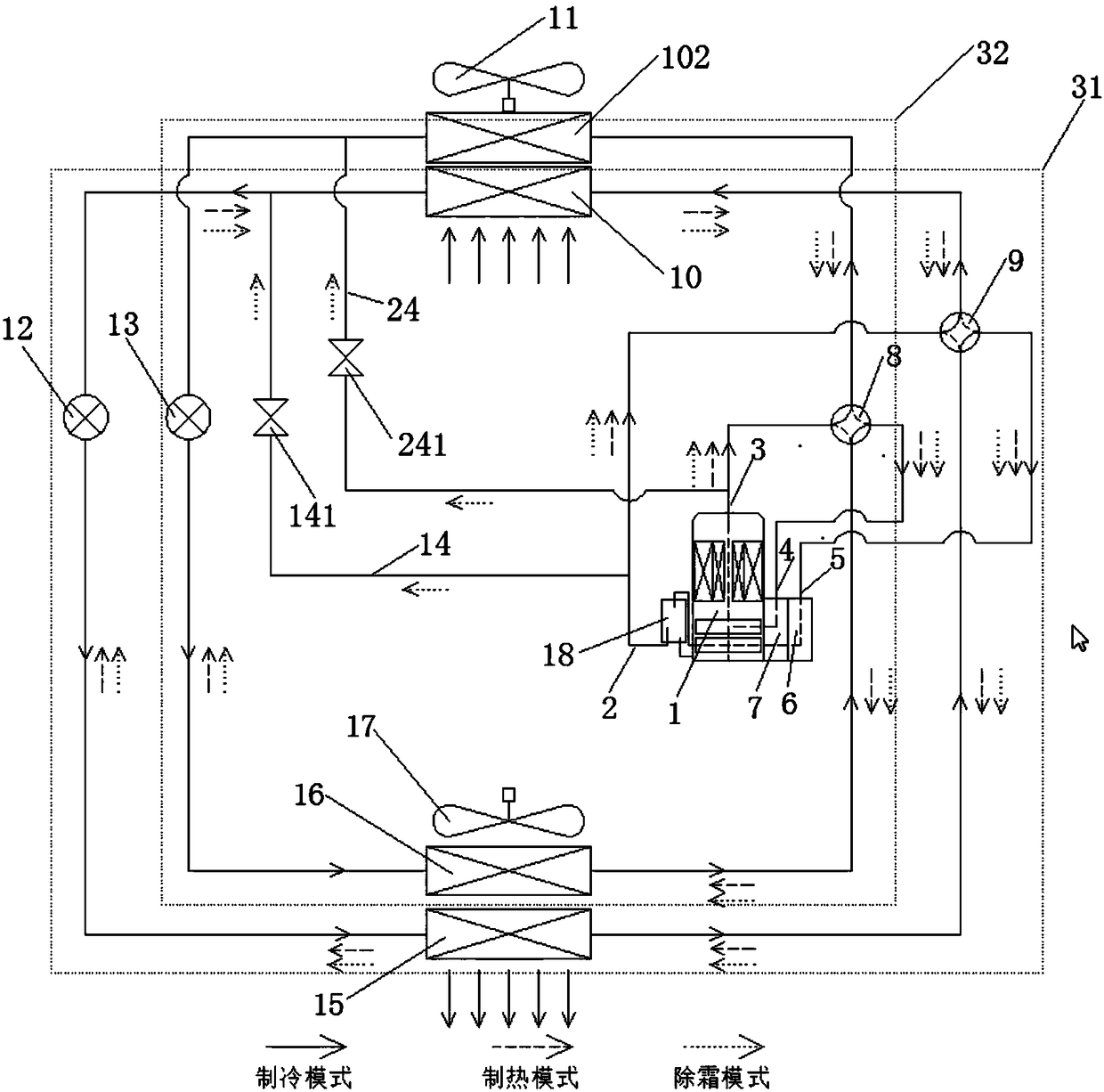
[0051] Such as image 3 As shown, the at least one outdoor heat exchanger includes a first outdoor heat exchanger 10 and a second outdoor heat exchanger 102; the first indoor heat exchanger 10, the first outdoor heat exchanger 12 and the The compressor 1 forms a first circulation loop 31, the second indoor heat exchanger 102, the second outdoor heat exchanger 16 and the compressor 1 form a second circulation loop 32, and the at least one bypass pipeline Including two bypass pipelines; the first circulation circuit 31 is provided with a first bypass pipeline 14, and the second circulation circuit 32 is provided with a second bypass pipeline 24, so that the first circulation The circuit 14 and the second circulation circuit 24 can perform defrosting alternately.
[0052] The first indoor heat exchanger 15 is connected to the first outdoor heat exchanger 10 through a first throttling device 12 , and the connection between the second indoor heat exchanger 16 and the second outdoo...
PUM
 Abstract
Description
Claims
Application Information
 - R&D
- Intellectual Property
- Life Sciences
- Materials
- Tech Scout
- Unparalleled Data Quality
- Higher Quality Content
- 60% Fewer Hallucinations
Browse by: Latest US Patents, China's latest patents, Technical Efficacy Thesaurus, Application Domain, Technology Topic, Popular Technical Reports.
© 2025 PatSnap. All rights reserved.Legal|Privacy policy|Modern Slavery Act Transparency Statement|Sitemap|About US| Contact US: help@patsnap.com