A milling machine auxiliary device

An auxiliary device, milling machine technology, applied in metal processing equipment, maintenance and safety accessories, metal processing machinery parts, etc., can solve problems such as damage, falling milling machine, etc., to achieve stable and reliable operation.

Inactive Publication Date: 2019-07-30
NANJING CHENWEI MACHINERY MFG CO LTD
View PDF10 Cites 0 Cited by
  • Summary
  • Abstract
  • Description
  • Claims
  • Application Information

AI Technical Summary

Problems solved by technology

[0003] The present invention intends to provide an auxiliary device for milling machines to solve the problem that the milling machine will be damaged if the counterweight of the existing milling machine falls after being used for a long time

Method used


Image

  • A milling machine auxiliary device
  • A milling machine auxiliary device
  • A milling machine auxiliary device

Examples


Embodiment Construction

[0016] Further detailed explanation through specific implementation mode below:

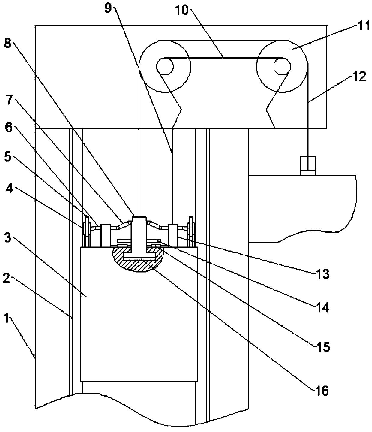
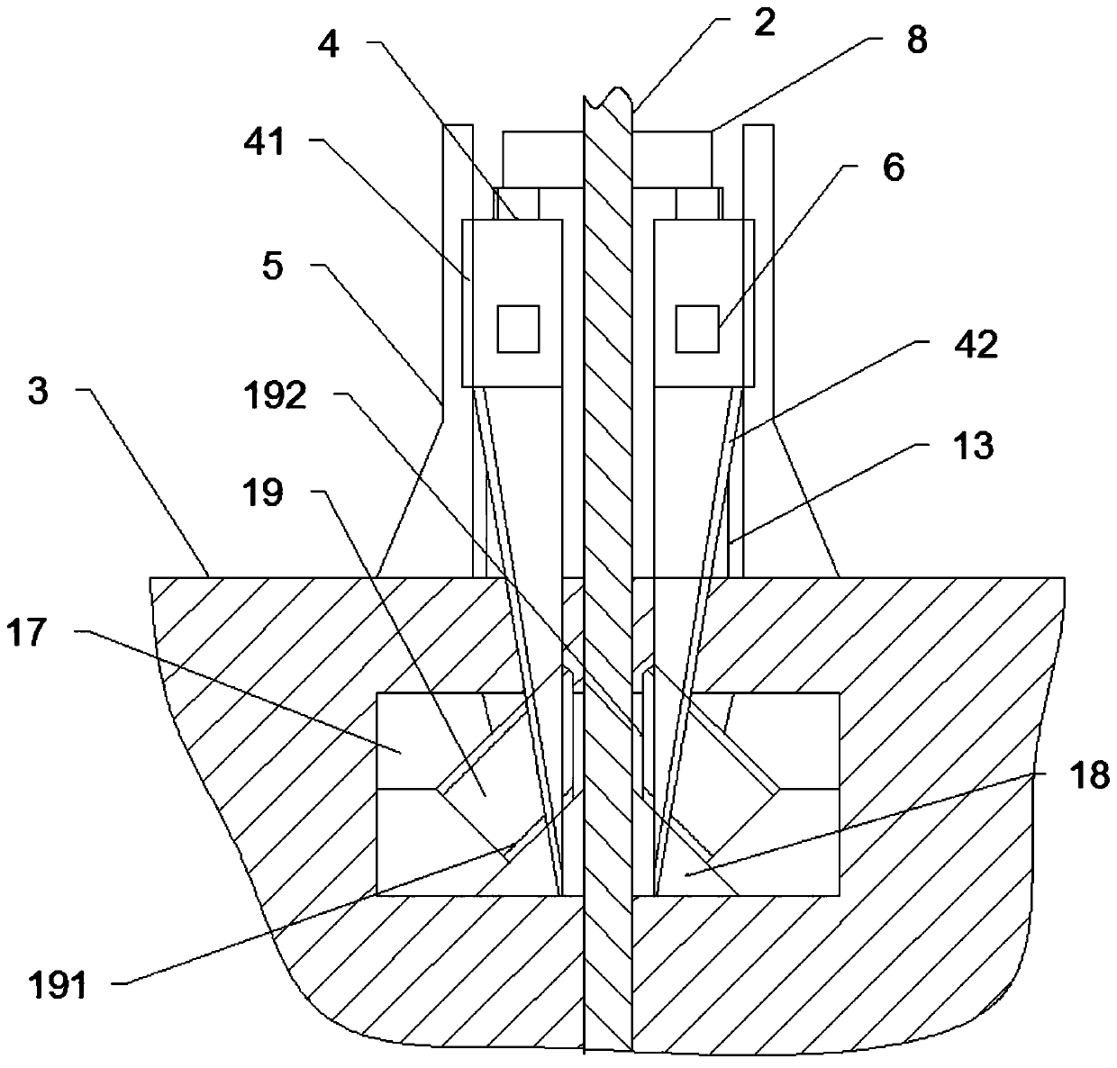
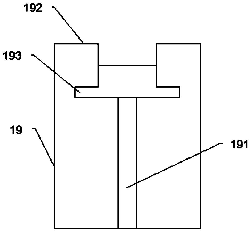
[0017] The reference signs in the accompanying drawings of the description include: column 1, guide rail 2, counterweight 3, push block 4, slide edge 41, slide bar 42, guide plate 5, push rod 6, connecting rod 7, hoisting block 8, accompanying Cable 9, pulley seat 10, pulley 11, connecting rope 12, support block 13, magnet plate 14, electromagnet 15, T-shaped groove 16, upper guide block 17, lower guide block 18, brake block 19, guide groove 191, Butt against end 192, slideway 193.

[0018] The embodiment is basically as attached figure 1 Shown: an auxiliary device for a milling machine, including a column 1, a counterweight 3, a boring box, a connecting rope 12 and a pulley seat 10 with a pulley 11, the middle part of the pulley seat 10 is sunken inward, and there are two pulleys 11, two Two pulleys 11 are arranged side by side on the upper end of the pulley seat 10, and the connecting rope 12...


PUM


Abstract

The invention discloses an auxiliary device for a milling machine. The device comprises a column, a balancing weight, a boring box, a connection rope and a pulley base with pulleys, the connection rope penetrates through the pulleys and is fixedly connected with the balancing weight and the boring box separately, the boring box is driven to move up and down by a motor, the column is hollow, and guide rails are arranged on the two opposite inner side walls of the column; a hoisting block which can move up and down is connected to the top of the balancing weight and connected with the connectionrope, guide grooves which are matched with the guide rails are formed in the outer side wall of the balancing weight, and braking mechanisms are arranged in the guide grooves; a transmission mechanism which is connected with the braking mechanisms is arranged on the balancing weight at the outer side of the hoisting block. According to the scheme, after the connection rope is fractured and the hoisting block falls down, the braking mechanisms can be driven to abut against the guide rails to brake the balancing weight, and the problem can be effectively avoided that the balancing weight fallsdown and the milling machine is damaged.

Description

technical field [0001] The invention relates to the field of mechanical processing equipment, in particular to an auxiliary device for a milling machine. Background technique [0002] In the current boring and milling machine field, especially the counterweight of the boring and milling machine, the pulley seat is arranged on the top of the column, the pulley is arranged along the axial horizontal direction, the weight of the counterweight and the boring box are matched, and the counterweight and the boring box are respectively located on the pulley The two sides are lower than the height of the pulley, and the connecting rope passes through the pulley and is respectively fixed on the counterweight and the boring box. The motor drives the boring box to move up and down, and the counterweight moves up and down along the steel pipe on the inner wall of the column. When moving up and down, the counterweight will shake left and right, causing abnormal noise, and the counterweigh...

Claims


Application Information

Patent Timeline
Patent Type & Authority Patents(China)
IPC IPC(8): B23Q11/00
CPCB23Q11/001
Inventor 欧番
Owner NANJING CHENWEI MACHINERY MFG CO LTD
Why Eureka
Try Eureka