
Friction nanogenerator and manufacturing method thereof

A nanogenerator and triboelectric sequence technology, applied in the nano field, can solve the problems of expensive equipment and difficult to control the microstructure and morphology, and achieve the effects of improving output, easy miniaturization, and improving friction efficiency.

Active Publication Date: 2018-06-05
BEIJING INST OF NANOENERGY & NANOSYST
View PDF3 Cites 3 Cited by
  • Summary
  • Abstract
  • Description
  • Claims
  • Application Information

AI Technical Summary

Problems solved by technology

Currently commonly used methods such as plasma etching, ion implantation, etc. often require expensive equipment, and the morphology of the microstructure is difficult to control

Method used


Image

  • Friction nanogenerator and manufacturing method thereof
  • Friction nanogenerator and manufacturing method thereof
  • Friction nanogenerator and manufacturing method thereof

Examples


no. 1 example

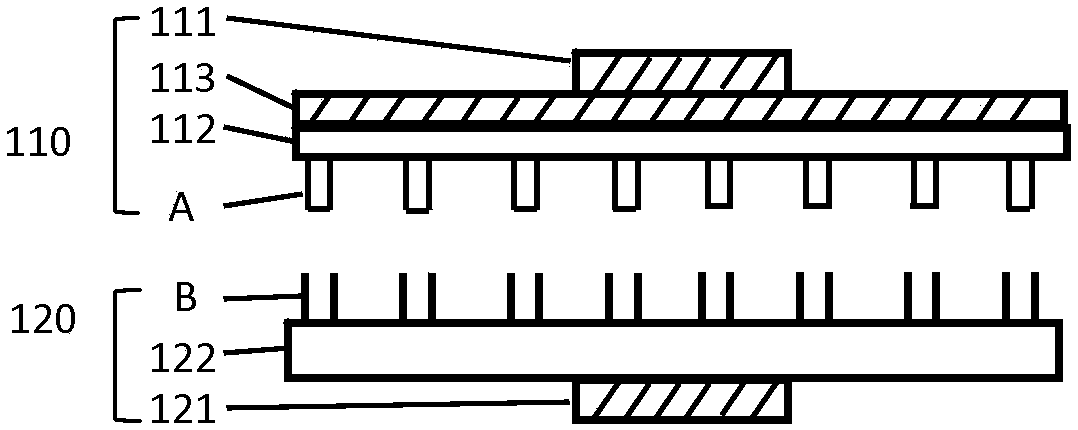
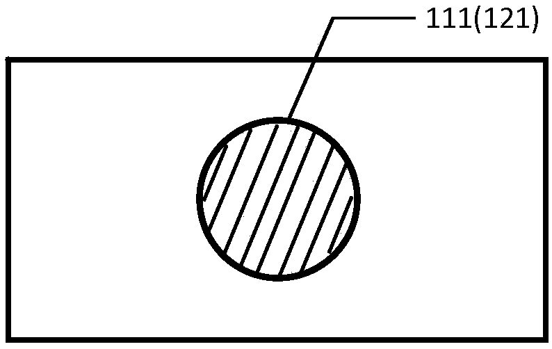
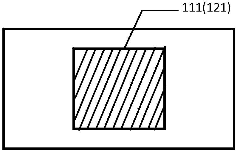
[0046] In Embodiment 1 of the present invention, a contact-separation friction nanogenerator is provided. figure 1 It is a schematic structural diagram of a friction nanogenerator packaged according to an embodiment of the present invention. Please refer to figure 1 , the present embodiment contact-separation friction nanogenerator comprises:

[0047] The first friction unit 110 includes a first magnetic part 111, a first friction layer 112 and an electrode layer 113, the electrode layer is formed outside the first friction layer, and the first magnetic part is formed on the electrode layer outside;

[0048] The second friction unit 120 is arranged opposite to the first friction unit, and the second friction unit includes a second magnetic part 121 and a second friction layer 122; the second magnetic part is formed on the second friction outside of the unit; where,

[0049] The first and second magnetic parts are oppositely arranged with the same poles, that is, N and N po...

no. 3 example

[0066] Image 6 It is a schematic structural diagram of the encapsulated triboelectric nanogenerator according to Embodiment 3 of the present invention. Please refer to Image 6 , the present embodiment contact-separation friction nanogenerator comprises:

[0067] The first friction unit 310, which includes a first friction layer 312 and an electrode layer 313, the first friction layer is formed of magnetic powder material and high molecular polymer;

[0068] a second friction unit 320, which is arranged opposite to the first friction unit, and the second friction unit includes a second friction layer 322 formed of a conductive magnetic material;

[0069] The opposite sides of the first friction unit and the second friction unit have the same polarity, so as to separate the first and second friction units after contact;

[0070] The materials on the opposite surfaces of the first friction unit and the second friction unit have different triboelectric series. During the proc...


PUM


Abstract

The invention provides a friction nanogenerator and a manufacturing method thereof. The friction nanogenerator comprises a first friction unit and a second friction unit, wherein the first friction unit comprises a first magnetic part; the second friction unit is arranged oppositely to the first friction unit, the materials on the opposite surfaces of the two have different friction electrode orders, the second friction unit comprises a second magnetic part, the first magnetic part and the second magnetic part are arranged with the same poles corresponding; and relative movement between the first friction unit and the second friction unit is realized through same-pole repulsion. The friction nanogenerator provided in the invention has the advantages of stable output after long-time use, simple structure, safety and reliability, low cost, high output and simple manufacturing process.

Description

technical field [0001] The invention relates to the field of nanotechnology, in particular to a friction nanogenerator. Background technique [0002] Harvesting and converting energy through nanotechnology plays a key role in the design and fabrication of self-generating and self-driving nanosystem devices. Since Professor Wang Zhonglin from the Georgia Institute of Technology invented the triboelectric nanogenerator, people have successively developed triboelectric nanogenerators based on different materials and structures. The generator mainly utilizes the difference in the triboelectrode sequence of the material to realize electron transfer in the process of friction contact, and drive the free electron flow to move through the potential difference. Nanogenerators can collect energy from the surrounding environment to generate electricity, convert mechanical energy into electrical energy, and drive electronic devices to operate. Compared with traditional electromagnetic...

Claims


Application Information

Patent Timeline
Patent Type & Authority Applications(China)
IPC IPC(8): H02N1/04
CPCH02N1/04
Inventor 李舟赵超超谈溥川李虎王华英李喆邹洋
Owner BEIJING INST OF NANOENERGY & NANOSYST
Learn More