Punching and grinding integrated device

A punching and integrated technology, applied in the direction of grinding/polishing safety devices, grinding machines, grinding/polishing equipment, etc., can solve the problems of unsightly appearance, complicated operation, and affecting the quality of use, so as to save energy and improve work efficiency Effect

Active Publication Date: 2019-05-17
徐州天骋智能科技有限公司
View PDF5 Cites 0 Cited by
  • Summary
  • Abstract
  • Description
  • Claims
  • Application Information

AI Technical Summary

Problems solved by technology

[0002] In the actual production process, the workpiece needs to be punched due to some special requirements after casting, because burrs and particles often appear on the surface of the newly cast workpiece, which is not only unsightly, but also affects its use quality , so it is necessary to remove particles and impurities on the surface to obtain a flat surface
However, the existing punching processing equipment can only perform a single process of punching, and the grinding process after punching needs to be completed by using a grinding machine or a CNC machine tool.
Since the above-mentioned processing needs to be completed on different equipment, the workpiece needs to be clamped and positioned multiple times, and the operation is complicated and time-consuming.

Method used


Image

  • Punching and grinding integrated device
  • Punching and grinding integrated device

Examples


Embodiment Construction

[0022] The following is further described in detail through specific implementation methods:

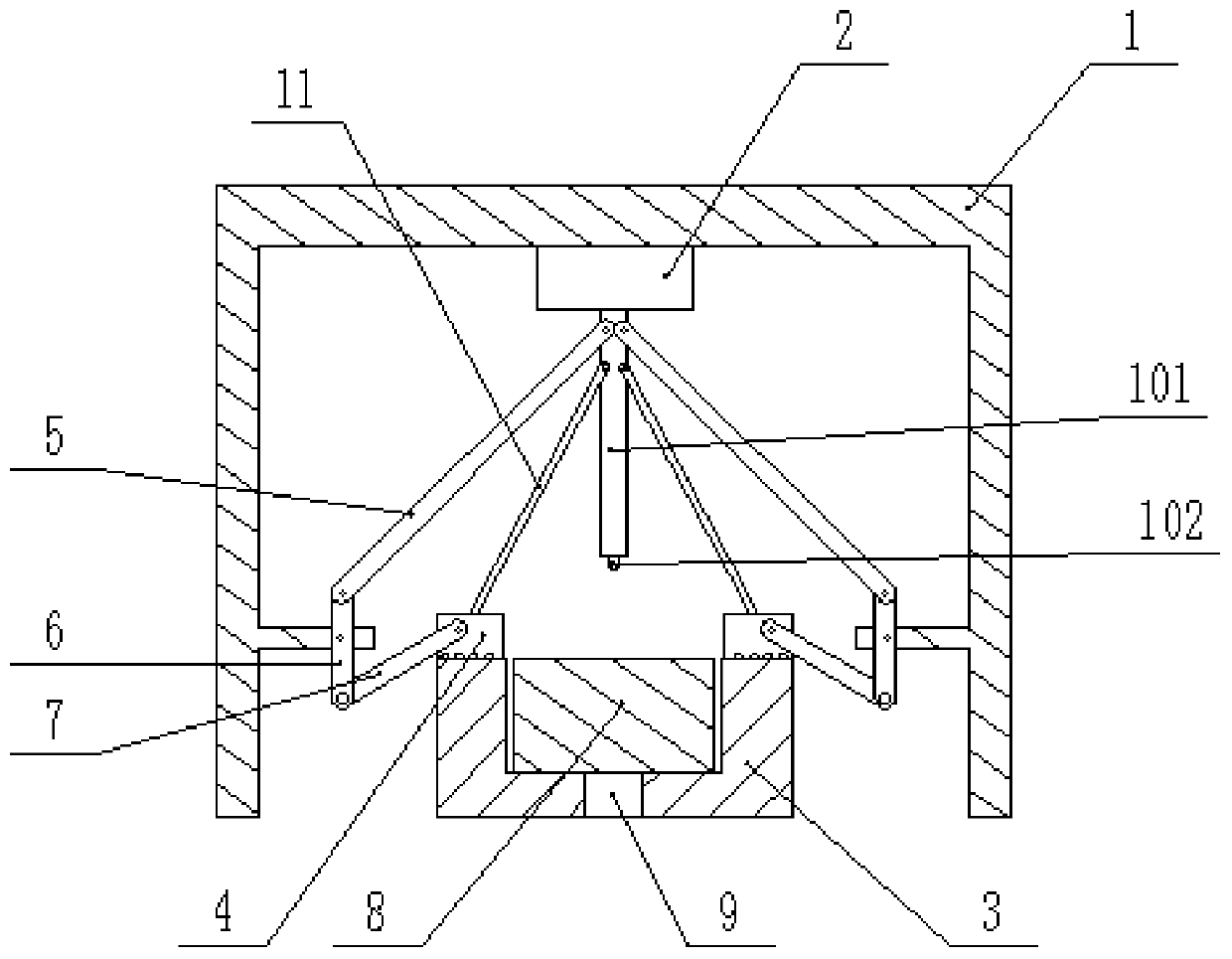
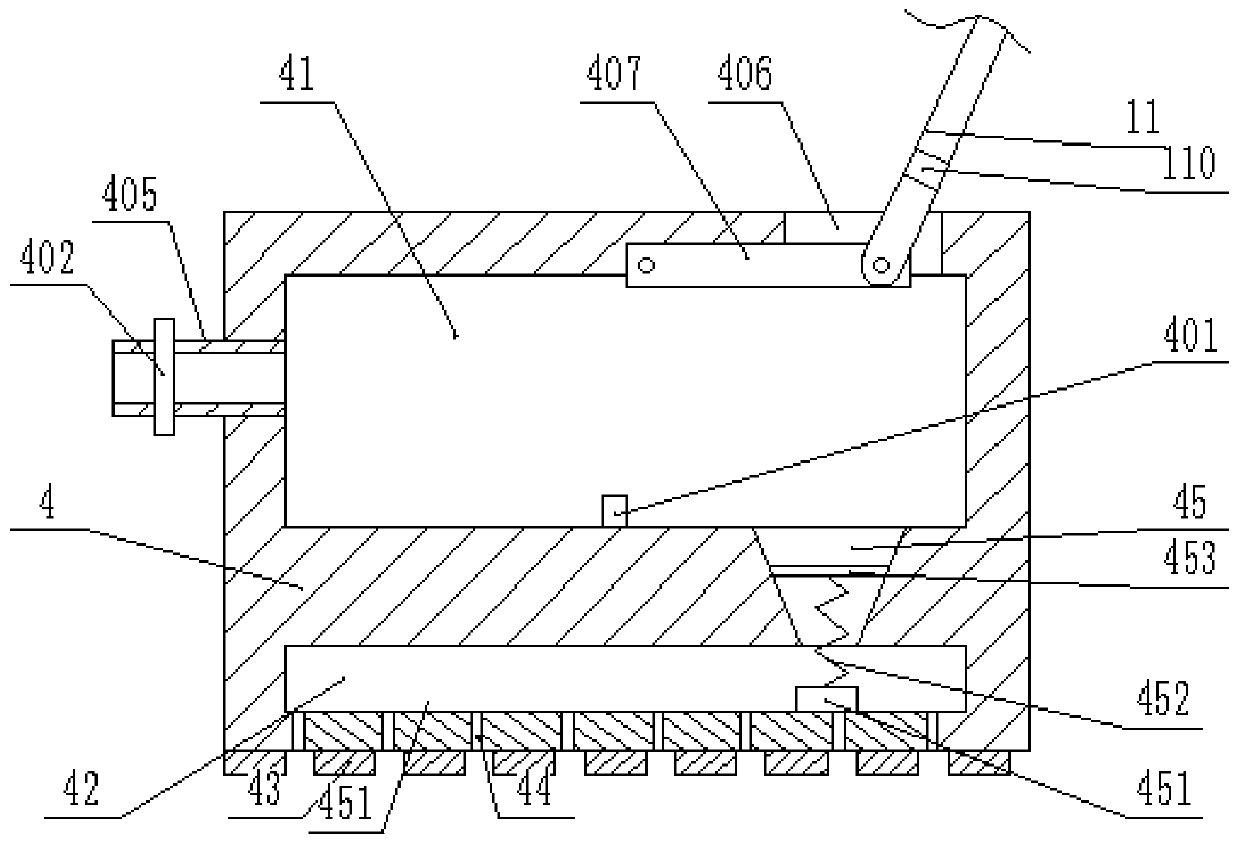
[0023] The reference signs in the drawings of the description include: frame 1, punch rod 101, punch 102, drive magnet 110, cylinder 2, fixed sleeve 3, grinding block 4, housing chamber 41, stopper 401, valve 402, water inlet pipe 405, push hole 406, partition 407, water outlet cavity 42, grinding protrusion 43, water outlet hole 44, communication hole 45, fixed block 451, supporting spring 452, moving magnet 453, first connecting rod 5, second connecting rod 6 , The third connecting rod 7, the workpiece 8, the chip hole 9, the push rod 11.

[0024] The embodiment is basically as attached figure 1 And attached figure 2 Shown:

[0025] The punching and polishing integrated device includes a frame 1, and also includes a punching machine, a grinding machine and a fixed sleeve 3 arranged in sequence from top to bottom. The fixed sleeve 3 is provided with a positioning groove. The up...


PUM


Abstract

The invention relates to a machining apparatus, in particular to a punching and polishing apparatus, comprising a frame, a punching machine, a polishing machine and a fixing sleeve, wherein the punching machine, the polishing machine and the fixing sleeve are arranged from top to bottom; the upper surface of the fixing sleeve is flush with the upper surface of a workpiece; the polishing machine comprises two polishing units symmetrically arranged on the left and right of a vertical axis of the fixing sleeve; each polishing unit comprises a polishing block and a linkage; a receiving cavity forstoring water is arranged in each polishing block; a partition and a push rod to push the partition to rotate are arranged in each receiving cavity, and the partition is horizontally hinged to the upper wall of a water storage cavity, while the other end of the partition is hinged to the push rod that is provided with a driving magnet; each push rod is also hinged to a punch rod; each partition may divide the corresponding receiving cavity into two chambers; the bottom of each receiving cavity is provided with a connection hole. The lower surface of each connection hole is provided with a water outlet. The linkages and the receiving cavities allow punching, polishing and washing to be carried out at the same, so that workpiece machining speed is increased; clamping the workpiece is not required, so that time and manpower are saved.

Description

technical field [0001] The invention relates to machining equipment, in particular to a punching and grinding integrated device. Background technique [0002] In the actual production process, the workpiece needs to be punched due to some special requirements after casting, because burrs and particles often appear on the surface of the newly cast workpiece, which is not only unsightly, but also affects its use quality , so it is necessary to remove the particles and impurities on the surface to obtain a flat surface. However, the existing punching processing equipment can only perform the single processing of punching, and the grinding process after punching needs to be completed by using a grinding machine or a numerically controlled machine tool. Since the above-mentioned processing needs to be completed on different equipment, the workpiece needs to be clamped and positioned multiple times, and the operation is complicated, time-consuming and labor-intensive. Contents ...

Claims


Application Information

Patent Timeline
Patent Type & Authority Patents(China)
IPC IPC(8): B23P23/00B21D28/24B24B9/04B24B55/06
CPCB21D28/24B23P23/00B24B9/04B24B55/06
Inventor 寇瑞东
Owner 徐州天骋智能科技有限公司
Why Eureka
Try Eureka