Eureka AIR delivers breakthrough ideas for toughest innovation challenges, trusted by R&D personnel around the world.

Methods and apparatuses for displaying energy savings from an HVAC system

Active Publication Date: 2011-06-30
SCHNEIDER ELECTRIC USA INC
View PDF18 Cites 174 Cited by
  • Summary
  • Abstract
  • Description
  • Claims
  • Application Information

AI Technical Summary

Benefits of technology

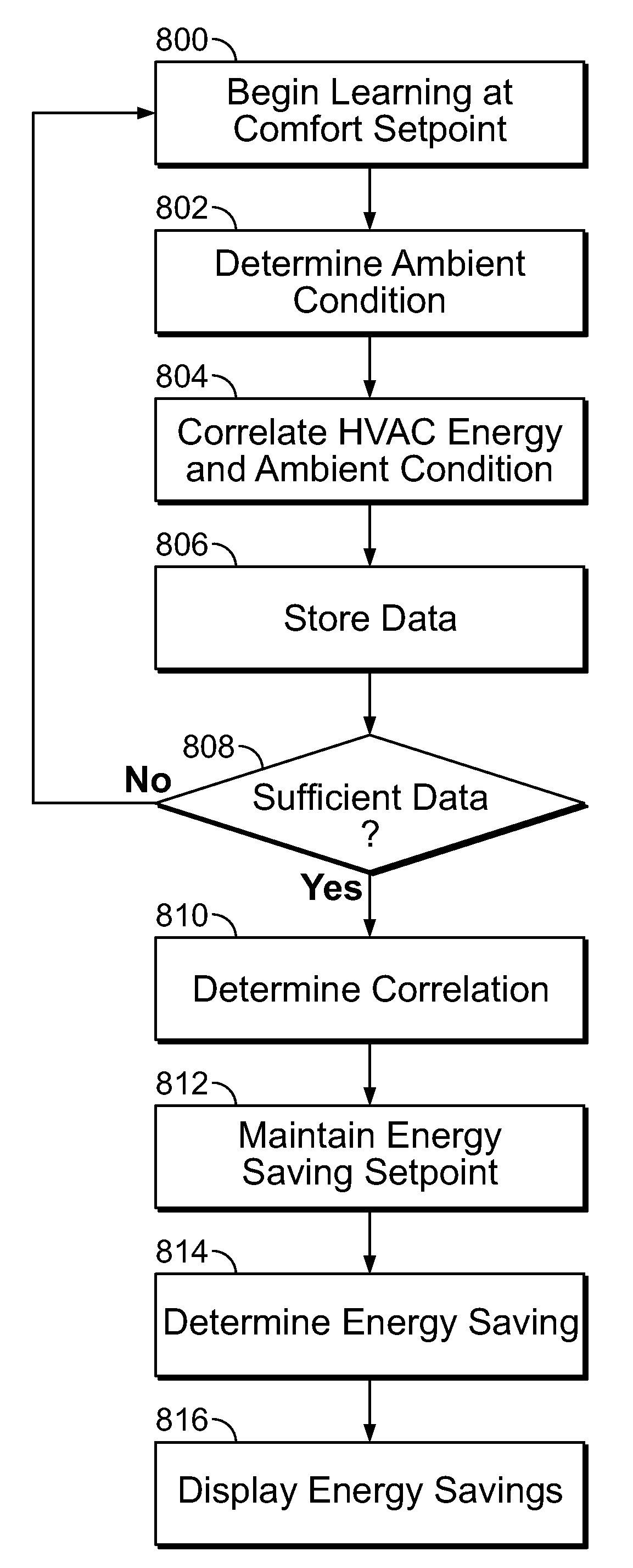
[0005]According to at least some aspects of the present disclosure a method of determining energy savings from an HVAC system in a building operating in an energy saving mode is disclosed. The HVAC system is run to maintain a comfort mode temperature during a learning period. The energy consumed by the HVAC system at multiple outside ambient conditions during the learning period is determined. A correlation between a specific ambient condition and energy consumed by the HVAC system is determined. The HVAC syst

Problems solved by technology

However, the energy savings from such time-based programmed setpoint temperatures as compared to the comfort temperature that is set during the day is unknown to a user.
This specification has been confusing to users as to how to achieve energy savings from programmable thermostats.
Even if the new specification is not finalized, the old Energy Star specification will be suspended due to the confusion to users.
Presently, users that invest in programmable thermostats to save energy and money do not have any ready means to determine how much energy and money is being truly saved.
The programmable thermostats therefore are arbitrarily set at different temperatures, which may or may not save the user money and energy.
Therefore, the present known programmable thermostats do not provide energy savings feedback to allow a user to adjust temperature setpoints and times based on how the building environment responds to changes in the internal and external environments.

Method used


Image

  • Methods and apparatuses for displaying energy savings from an HVAC system
  • Methods and apparatuses for displaying energy savings from an HVAC system
  • Methods and apparatuses for displaying energy savings from an HVAC system

Examples


Embodiment Construction

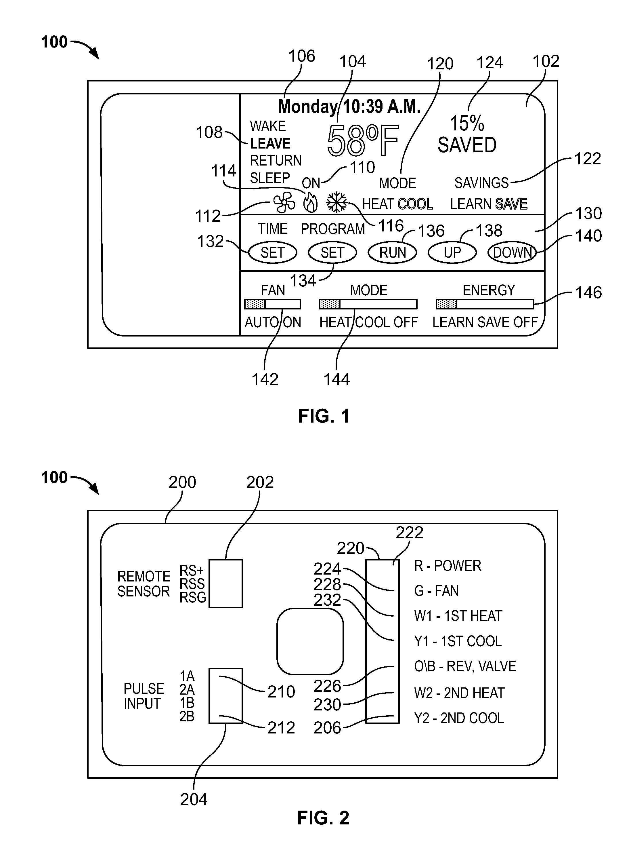
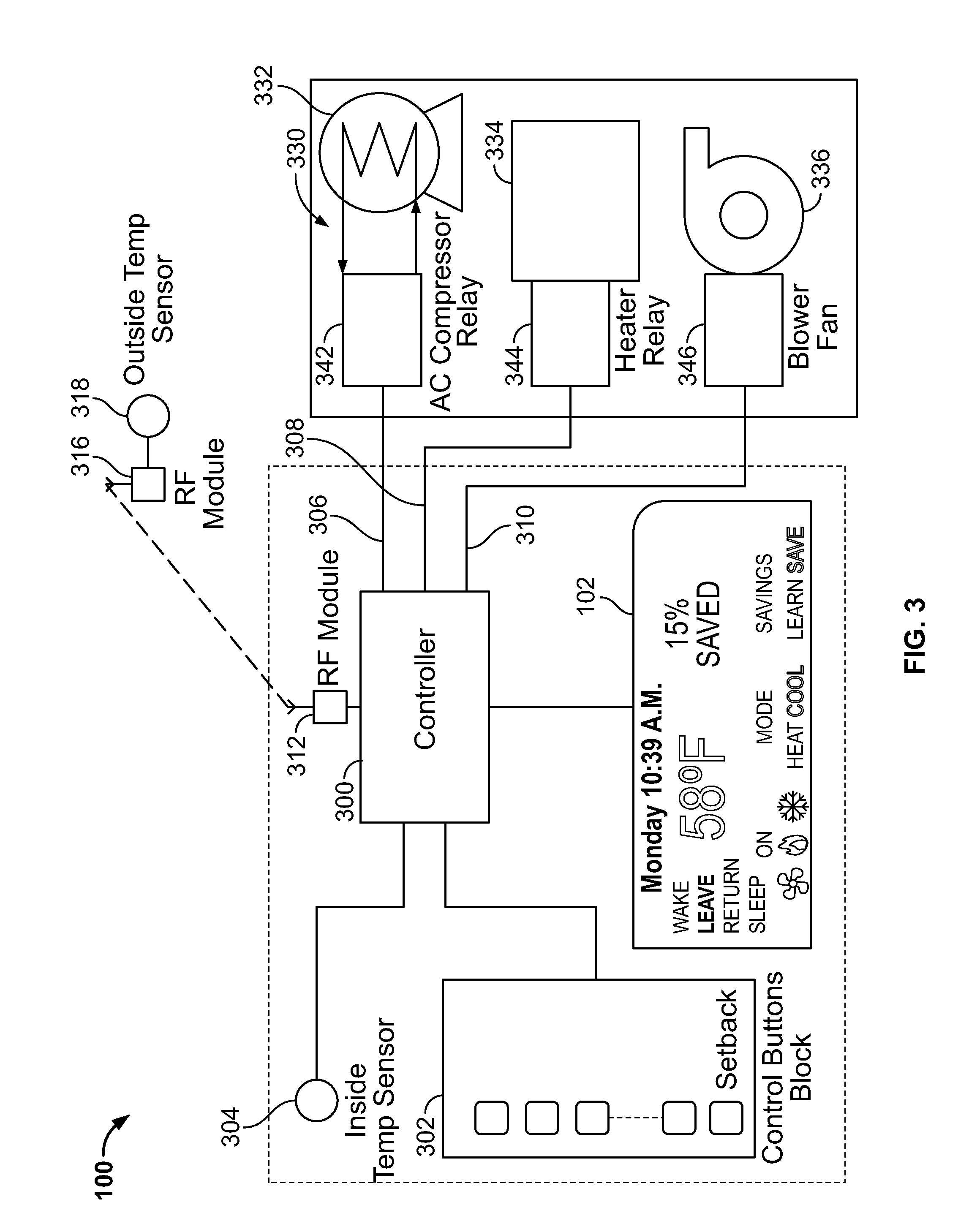
[0018]Referring to FIG. 1, a programmable thermostat 100 is shown with a coverplate (not shown) removed. The thermostat 100 includes a display 102 that shows the current operation and status of the HVAC system. The display 102 shows the temperature 104, the date and time 106, and a status field 108. The temperature 104 is the actual room or indoor temperature measured by the thermostat 100. In this example, the temperature is expressed in Fahrenheit but other units of measurement such as Celsius can be used. The status field 108 includes different setpoints that may be programmed such as a Wake setpoint, a Leave setpoint, a Return setpoint, and a Sleep setpoint. The display 102 also includes an “on” indicator 110 with an appropriate set of icons such as a fan icon 112, a heat icon 114, and a cooling icon 116 that indicate the mode of the HVAC system that is currently activated. In this example, the heat icon 114 is highlighted indicating that the heating system of the HVAC system is...


PUM


Abstract

A method and system of determining and displaying energy savings from an HVAC system operating in an energy saving mode. The HVAC system is operated to maintain a comfort mode temperature during a learning period. The energy consumed by the HVAC system at multiple outside ambient conditions during the learning period is determined. The correlation between a specific ambient condition and energy consumed by the HVAC system is determined. The HVAC system is run to maintain an energy saving setpoint temperature. The energy consumed by the HVAC system is determined at an ambient condition while maintaining the energy saving setpoint temperature. The energy savings are calculated as a function of the difference between the energy that would have been consumed by the HVAC system at the ambient condition based on the determined correlation and the energy consumed by the HVAC system while maintaining the energy saving setpoint temperature at the ambient condition

Description

FIELD OF THE INVENTION[0001]The present invention relates generally to the determination of energy data and, in particular, to methods for estimating energy savings of an HVAC system.BACKGROUND[0002]As is well-known, thermostats control heating, ventilation, and air conditioning (“HVAC”) systems in buildings. A non-programmable thermostat allows a user, such as an occupant or building manager, to set one setpoint temperature for the heating season and one setpoint temperature for the cooling season to control the HVAC system. When the measured indoor temperature is below or above these setpoint temperatures, the HVAC system is activated. A programmable thermostat allows a user to program setpoint temperatures for different times of the day. For example, in the heating season, many users still set the thermostat to a lower set-back temperature at night. This temperature set-back reduces the amount of time that the HVAC system is activated in order to maintain the lower temperature an...

Claims


Application Information

Patent Timeline
IPC IPC(8): G06F1/28G05D23/19G06F3/048G06F15/18
CPCF24F2011/0094F24D19/1048F24F11/47
Inventor PARKER, KEVIN L.FILIPPENKO, ALEXANDER
Owner SCHNEIDER ELECTRIC USA INC
Why Eureka
Eureka Blog
Learn More