Reference signal transmission method and device
A reference signal and transmission method technology, which is applied in the field of reference signal transmission method and equipment, can solve the problem of high DCI overhead, and achieve the effect of cost saving
- Summary
- Abstract
- Description
- Claims
- Application Information
AI Technical Summary
Problems solved by technology
Method used
Image
Examples
Embodiment 1
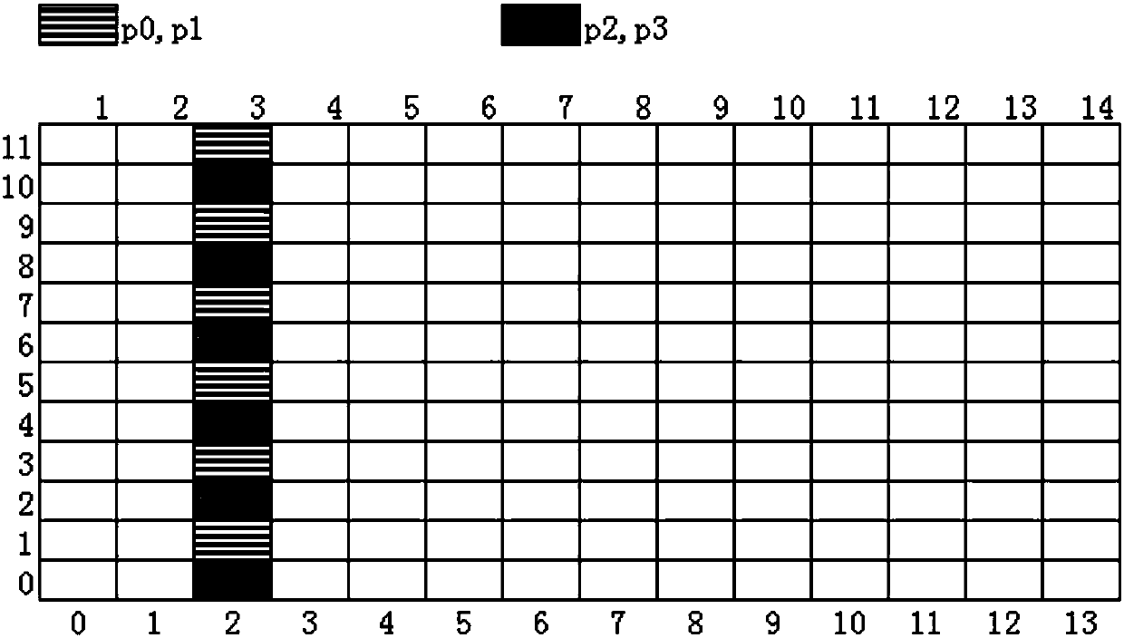
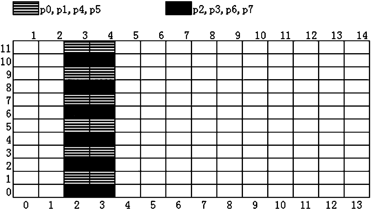
[0079] Currently, each codeword (CW) in LTE has a corresponding MCS, RV, and NDI indication field, and there are a total of 2 codewords corresponding to 2 transmission blocks (TB, transmission block) to transmit data. LTE users support multi-layer transmission, and each data layer corresponds to a DMRS port. For initial transmission, when the number of data layers allocated by a user is greater than 1, 2 TB are required for transmission. In NR, for initial transmission, when the number of data layers allocated by a user is greater than 4, only 2 TB are required for transmission. That is to say, in one CW, the number of data layers or the number of DMRS ports allocated to the UE can be one of 1, 2, 3, and 4. At the same time, in order to support multi-user MIMO, each DMRS port may have a different scrambling ID, similar to n in LTE SCID .In MU-MIMO, often one user is one CW. Moreover, in MU-MIMO, NR supports non-transparent transmission, that is, the base station needs to te...
Embodiment 2
[0104] In NR, the uplink transmission is different from the downlink, because the uplink is divided into the case with channel reciprocity and the case without channel reciprocity. When there is no channel reciprocity, the UE has no way to obtain the uplink precoding matrix and the number of transmission layers by estimating the downlink CSI-RS (channel state information reference signal). At this time, the base station needs to notify the user of the precoding matrix index (TPMI: Transmit Precoding Matrix Indicator) when scheduling data. We call this scheduling method a codebook-based transmission method because TPMI is an index in the uplink codebook. Of course, the same as the downlink, the base station also needs to notify the user of the port information of the DMRS.
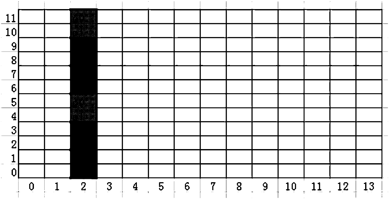
[0105] As for the reference signal, an important point different from LTE in NR is that phase noise tracking reference signal (PTRS: phase tracking reference signal) is introduced in NR. The main purpose is...
Embodiment 3
[0145] For uplink, when there is channel reciprocity, the base station can calculate the precoding matrix for uplink transmission according to the SRS sent by the user, and the user can also calculate the equivalent uplink precoding matrix through the downlink CSI-RS, so when scheduling data It is not necessary to notify the user of the index of the precoding matrix used for scheduling, that is, TPMI (Transmit recoding Matrix Indicator). At this time, the base station can configure several SRI (SRS resource indicators) for the user. The precoding used by the user when sending uplink data is the precoding of the SRS corresponding to the SRI. The SRS resource indicated by the SRI is the one that the UE has sent before. . For convenience, the SRS resources indicated by one SRI are all single-port SRSs, and one SRS resource may correspond to one DMRS port. If the base station indicates 2 SRIs to the user in the DCI, it corresponds to 2 DMRS ports, that is, 2 data layers. When th...
PUM
 Abstract
Description
Claims
Application Information
 - R&D Engineer
- R&D Manager
- IP Professional
- Industry Leading Data Capabilities
- Powerful AI technology
- Patent DNA Extraction
Browse by: Latest US Patents, China's latest patents, Technical Efficacy Thesaurus, Application Domain, Technology Topic, Popular Technical Reports.
© 2024 PatSnap. All rights reserved.Legal|Privacy policy|Modern Slavery Act Transparency Statement|Sitemap|About US| Contact US: help@patsnap.com


