IGBT heat sensitive electric parameter extraction device
A technology sensitive to electrical parameters and heat, applied in measuring devices, measuring electricity, measuring electrical variables, etc., can solve problems such as increased on-state resistance, packaging defects, and slow response speed
- Summary
- Abstract
- Description
- Claims
- Application Information
AI Technical Summary
Problems solved by technology
Method used
Image
Examples
Embodiment 1
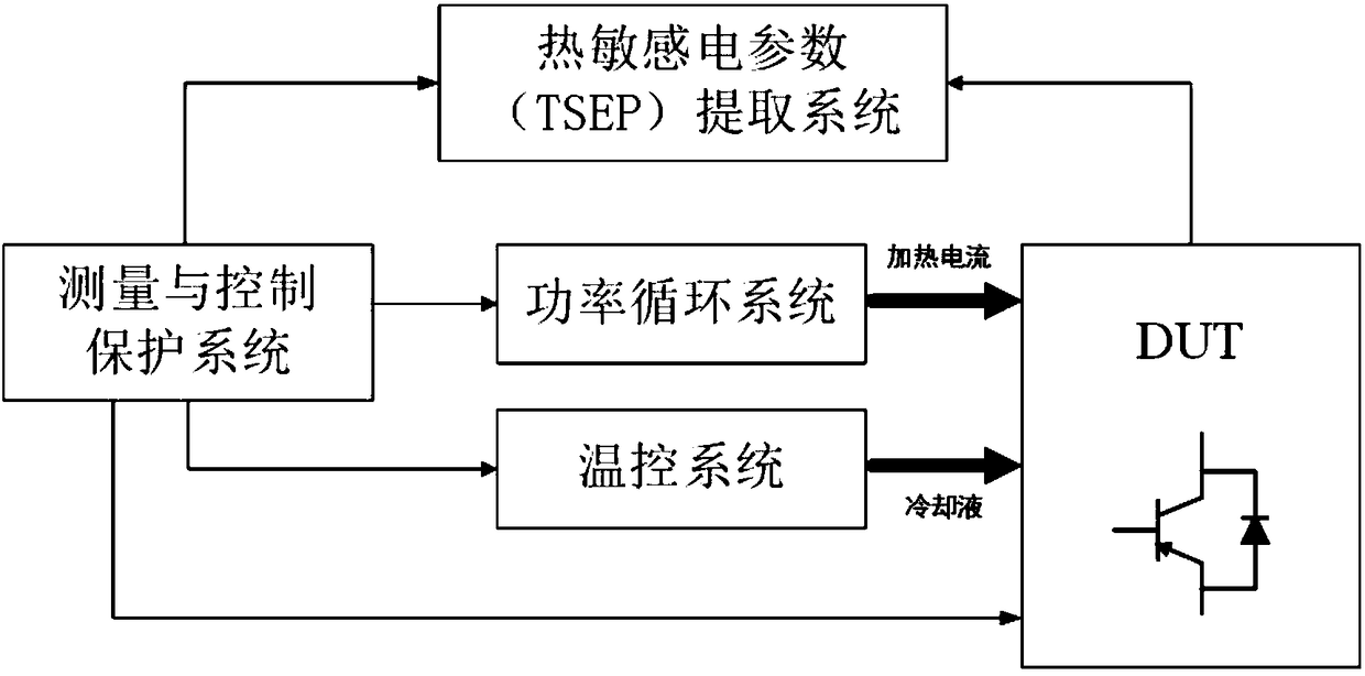
[0049] See figure 1 , figure 2 , image 3 with Figure 4 , A device for extracting thermally sensitive electrical parameters of IGBT, mainly includes a power cycle system 1, a thermally sensitive electrical parameter extraction system 2, a test station 3, a temperature control system 4, and a measurement and control protection system 5.
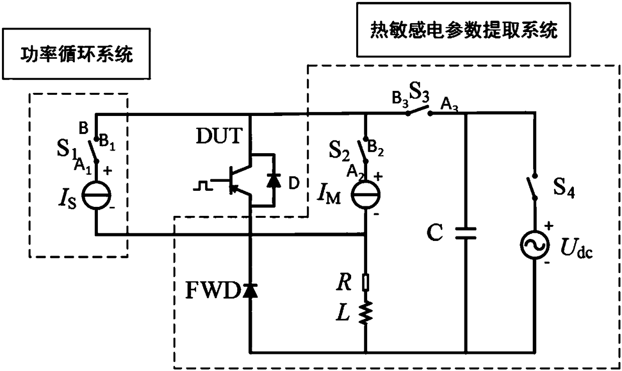
[0050] The circuit structure of the power cycle system 1 is: a power cycle power supply control switch S 1 A 1 Terminal series power circulating current source Is.
[0051] The power circulation system 1 and the thermosensitive electric parameter extraction system 2 form a series loop.
[0052] Further, the power cycle system 1 and the thermosensitive electric parameter extraction system 2 work independently.
[0053] The thermosensitive electric parameter extraction system 2 mainly includes a static thermosensitive electric parameter extraction subsystem 201 and a dynamic thermosensitive electric parameter extraction subsystem 202.
[0054] Further,...
Embodiment 2
[0082] See Figure 5 , The steps for extracting IGBT static thermal sensitive electrical parameters are as follows:
[0083] 1) Follow Figure 1 to Figure 4 As described, the IGBT thermal sensitive electrical parameter extraction device is connected.
[0084] 2) Let the test current source control switch S 2 Closed, the power cycle power control switch S 1 , The energy storage system control switch S 3 And the energy storage power control switch S 4 Both remain disconnected.
[0085] 3) The signal source 504 outputs a trigger signal to the device under test 301.
[0086] 4) Collect the analog waveform signals of the voltage and current of the device under test 301 through the data acquisition card 501.
[0087] 5) Use the A / D conversion module 502 to convert the analog waveform signal into a digital waveform signal.
[0088] 6) The processor 503 receives and processes the digital waveform signal. The processor 503 controls the switch S to the power cycle 1 , The test current source con...
Embodiment 3
[0090] See Image 6 , The steps for extracting IGBT dynamic thermal sensitive electrical parameters are as follows:
[0091] 1) Follow Figure 1 to Figure 4 As described, the IGBT thermal sensitive electrical parameter extraction device is connected.
[0092] 2) Make the energy storage system control switch S 3 And the energy storage power control switch S 4 Closed, the power cycle power control switch S 1 And the test current source control switch S 2 Hold disconnect.
[0093] 3) The signal source 504 outputs a trigger signal to the device under test 301.
[0094] 4) Control the switching of the power device transistor on the test station 5 through the gate control signal of the measurement and control protection system 5.
[0095] 5) The data acquisition card 501 acquires the transient analog waveform signal of the switching process of the transistor.
[0096] 6) Utilize the A / D conversion module 502 to convert the analog waveform signal into a digital waveform signal.
[0097] 7) The ...
PUM
 Abstract
Description
Claims
Application Information
 - R&D
- Intellectual Property
- Life Sciences
- Materials
- Tech Scout
- Unparalleled Data Quality
- Higher Quality Content
- 60% Fewer Hallucinations
Browse by: Latest US Patents, China's latest patents, Technical Efficacy Thesaurus, Application Domain, Technology Topic, Popular Technical Reports.
© 2025 PatSnap. All rights reserved.Legal|Privacy policy|Modern Slavery Act Transparency Statement|Sitemap|About US| Contact US: help@patsnap.com


