Double-connecting-beam structure and construction method thereof

A connecting beam, one-way technology, applied in joists, girders, trusses and other directions, can solve problems such as large drawbacks, brittle failure, and overall structure reduction, achieve great economic value and social benefits, reduce the probability of brittle failure, The effect of prolonging the service life of the structure

Pending Publication Date: 2018-06-01
SHENZHEN UNIV
View PDF5 Cites 5 Cited by
  • Summary
  • Abstract
  • Description
  • Claims
  • Application Information

AI Technical Summary

Problems solved by technology

[0003] The traditional single-connection beam has the characteristics of small span and large section, so the stiffness of the single-connection beam is relatively large. Under the earthquake, the shear force and bending moment are very large, which not only makes it difficult to reinforce the section, but also is prone to brittle failure. The traditional The disadvantages of single beam
[0004] Although the traditional double-connected beam has the characteristics of reduced section and low stiffness, which can effectively reduce the bending moment and shear force, but as the force transmission member between the wall pier, the constraint of the double-connected beam on the wall pier is also reduced. Small, so that its integrity is lower than that of the corresponding single-beam shear wall structure, which is unfavorable for the structure's seismic resistance

Method used


Image

  • Double-connecting-beam structure and construction method thereof
  • Double-connecting-beam structure and construction method thereof
  • Double-connecting-beam structure and construction method thereof

Examples


Embodiment Construction

[0031] The following will clearly and completely describe the technical solutions in the embodiments of the present invention with reference to the accompanying drawings in the embodiments of the present invention. Obviously, the described embodiments are only some, not all, embodiments of the present invention. Based on the embodiments of the present invention, all other embodiments obtained by persons of ordinary skill in the art without making creative efforts belong to the protection scope of the present invention.

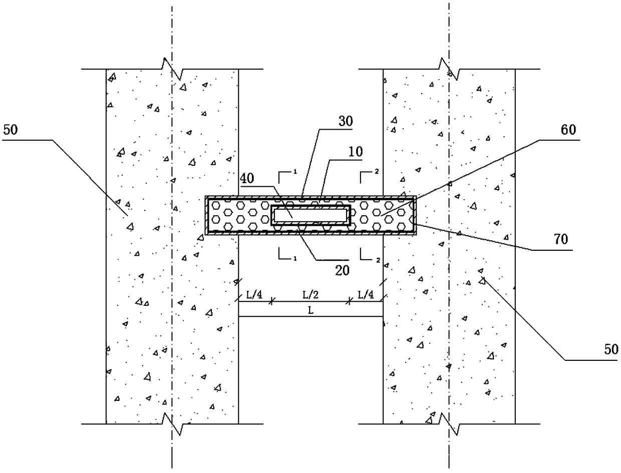
[0032] The purpose of the present invention is to provide a double connecting beam and its construction method, which ensures the integrity of the double connecting beam shear wall structural system, effectively reduces the bending moment borne by the connecting beam, and reduces the risk of brittle failure of the connecting beam in an earthquake. Probability, has high practical value.

[0033] In order to make the above objects, features and advantages of the...


PUM


Abstract

The invention belongs to the field of civil engineering, and discloses a double-connecting-beam structure. The double-connecting-beam structure comprises a square steel tube. The middle position in the length direction of the square steel tube is provided with a through hole body. The position between the square steel tube and the interior of the through hole body is filled with concrete to form an upper connecting beam and a lower connecting beam. The invention further discloses a construction method of the double-connecting-beam structure, and the construction method comprises the steps thatA, the square steel tube is made according to the design size; B, the middle position in the length direction of the square steel tube is provided with the through hole body, and the position, located outside the through hole body, of the interior of the square steel tube is filled with the concrete to form a connecting beam; and C, two shear wall templates are erected, the connecting beam of thesquare steel tube is placed between the two shear wall templates and connected with the two shear wall templates; and the two shear wall templates are poured, standard maintenance is conducted on theconcrete poured on the two shear walls, after the concrete strength meets requirements, the templates are dismantled, the wholeness of a double-connecting-beam shear wall structure system is ensured,the bending moment borne by the connecting beam is effectively reduced, and the probability of brittle failure of the connecting beam in an earthquake is decreased.

Description

technical field [0001] The invention belongs to the field of civil engineering, and in particular relates to a double connecting beam and a construction method thereof. Background technique [0002] Coupling beams refer to beams that connect wall piers to wall piers and are connected within the plane of the wall piers in the shear wall structure and frame-shear wall structure. Coupling beams, as force-transmitting components between wall piers, have an important impact on the seismic performance of structures. As the first line of defense against seismic energy consumption of structures, in order to avoid premature failure of wall piers, rational design of coupling beams is essential for improving shear wall performance. The mechanical performance plays a vital role. The traditional connecting beam is a single or double connecting beam structure, but it has the following disadvantages: [0003] The traditional single-connection beam has the characteristics of small span and...

Claims


Application Information

Patent Timeline
Patent Type & Authority Applications(China)
IPC IPC(8): E04C3/20
CPCE04C3/20
Inventor 管民生杜宏彪黄献奇
Owner SHENZHEN UNIV
Why Eureka
Try Eureka