LED lamp voltage stabilizing method and circuit adapted to fluctuation of input voltage automatically
A technology of LED lights and input voltage, which is applied in the field of circuit devices, can solve the problem that the constant current drive circuit is not suitable for the input current, etc., and achieve the effect of stable dimming, simple circuit structure, and elimination of flicker
- Summary
- Abstract
- Description
- Claims
- Application Information
AI Technical Summary
Problems solved by technology
Method used
Image

Examples
Embodiment 1
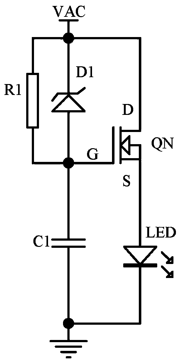
[0081] Embodiment one, see Figure 3A , the first embodiment is figure 2The actual application of the specific circuit, the present invention can automatically adapt to the fluctuation of the input voltage LED lamp voltage regulator circuit, including N-channel field effect transistor QN, LED lamp and voltage regulator D1, wherein the triode transistor is an N-channel type The field effect transistor QN, the adaptive voltage regulator module 100 is a voltage regulator tube D1; the anode of the LED lamp is electrically connected to the source S of the field effect transistor QN, and the drain D of the field effect transistor QN is connected to the input power supply The positive pole is electrically connected, and the negative pole of the LED lamp is electrically connected to the negative pole of the input power supply; both ends of the voltage regulator tube D1 are electrically connected between the positive pole of the input power supply and the grid G of the field effect ...
Embodiment 2
[0088] Embodiment two, see Figure 3B , the second embodiment is basically the same as the first embodiment, the difference is that the adaptive voltage regulation module 100 also includes a resistor R1 and a capacitor C1, that is, the adaptive voltage regulator module 100 is a voltage regulator tube D1, a resistor R1 and a capacitor C1; The resistor R1 is electrically connected between the positive pole of the input power supply and the gate G of the field effect transistor QN, it can also be said that the resistor R1 is connected in parallel with both ends of the voltage regulator tube D1, and the capacitor C1 is electrically connected with the gate G of the field effect transistor QN and the negative terminal of the input power supply. The LED lamp voltage stabilizing circuit of the second embodiment can effectively reduce the unnecessary loss caused by the high reverse breakdown voltage of the voltage stabilizing tube D1. The current is charged from the positive pole of th...
Embodiment 3
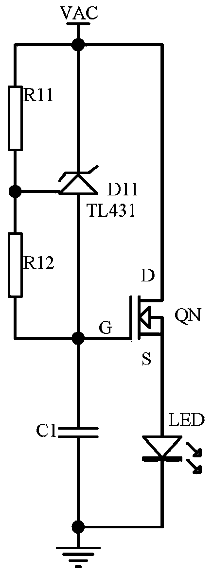
[0090] Embodiment three, see Figure 3C , the third embodiment is basically the same as the second embodiment, the difference is that the adjustable voltage regulator tube D11 is used instead of the voltage regulator tube D1, and the resistor R1 is replaced by two resistors R11 and R12, that is, the adaptive voltage regulator module 100 includes an adjustable voltage regulator tube D11, a resistor R11, a resistor R12 and a capacitor C1; both ends of the adjustable voltage regulator tube D11 are electrically connected between the positive pole of the input power supply and the gate G of the field effect transistor QN, wherein the adjustable voltage regulator The anode of the tube D11 is electrically connected to the gate G of the field effect transistor QN, the resistor R11 and the resistor R12 are connected in parallel to both ends of the adjustable voltage regulator tube D11 after being connected in series, and the detection voltage terminal of the adjustable voltage regulator...
PUM
 Abstract
Description
Claims
Application Information
 - R&D
- Intellectual Property
- Life Sciences
- Materials
- Tech Scout
- Unparalleled Data Quality
- Higher Quality Content
- 60% Fewer Hallucinations
Browse by: Latest US Patents, China's latest patents, Technical Efficacy Thesaurus, Application Domain, Technology Topic, Popular Technical Reports.
© 2025 PatSnap. All rights reserved.Legal|Privacy policy|Modern Slavery Act Transparency Statement|Sitemap|About US| Contact US: help@patsnap.com