Equivalent scrubbing machine for inner chambers of pump bodies of fuel oil injection pumps

A fuel injection pump and scrubbing machine technology, which is applied in the direction of grinding racks, grinding machine parts, and machine tools suitable for grinding the edge of workpieces, etc. It can solve the problems of poor plunger movement, difficult quality control of manual deburring Difficult to balance force control and other issues, to ensure the effect of deburring and avoid the effect of smoothness decline

Active Publication Date: 2018-05-25
无锡富泰盛精模科技有限公司
View PDF6 Cites 0 Cited by
  • Summary
  • Abstract
  • Description
  • Claims
  • Application Information

AI Technical Summary

Problems solved by technology

[0002] The camshaft hole and plunger hole on the pump body of the fuel injection pump are usually processed by fine boring or fine reaming. ) produces burrs, and these burrs will bring many adverse effects in the normal operation of the fuel injection pump body, such as the plunger movement is not smooth, the burr pollutes the oil body, etc. Therefore, when manufacturing the fuel injection pump body, it is necessary It is rarely necessary to remove the burrs in the inner cavity of the pump. The traditional deburring method is manual. Because the manual method is too subjective, it is impossible to achieve consistent brushing of each hole, and it is difficult to balance the force control. The quality of each pump body is deviated due to deburring, and even the quality of different plunger holes on the same pump body has a large deviation, or the phenomenon of scratching the hole wall. Therefore, manual deburring is difficult to control the quality and easily damages the cavity. Technical issues such as wall finish

Method used


Image

  • Equivalent scrubbing machine for inner chambers of pump bodies of fuel oil injection pumps
  • Equivalent scrubbing machine for inner chambers of pump bodies of fuel oil injection pumps
  • Equivalent scrubbing machine for inner chambers of pump bodies of fuel oil injection pumps

Examples


Embodiment Construction

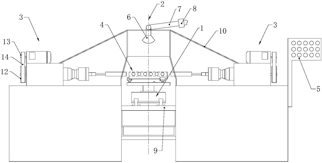
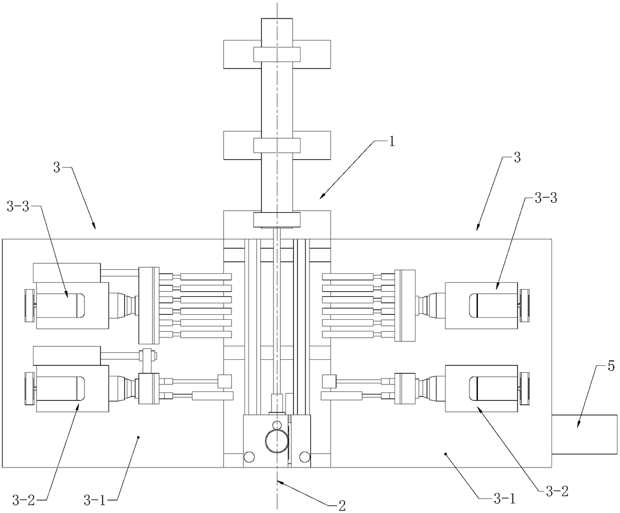
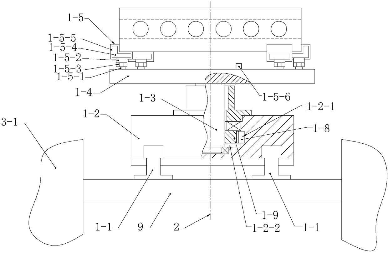
[0024] Such as Figure 1 to Figure 6The fuel injection pump body cavity brushing machine shown in the figure includes a workpiece positioning device 1, a brushing device 3 and a controller 5 symmetrically arranged on both sides of the workpiece positioning device 1, and the two brushing devices 3 are centered around the central axis of the workpiece positioning device 1. 2 is a symmetrical axis, and the scrubbing device 3 includes a machine platform 3-1, and a camshaft hole scrubbing mechanism 3-2 and a plunger arranged axially along the central axis 2 of the workpiece positioning device 1 are arranged on the upper end surface of the machine platform 3-1. A hole brushing mechanism 3-3, the camshaft hole brushing mechanism 3-2 includes a first driver 3-2-1 and a camshaft hole brush roller 3-2-2, and the first driver 3-2-1 drives the camshaft The hole brush roller 3-2-2 rotates and performs telescopic movement toward the workpiece positioning device 1 perpendicular to the centra...


PUM


Abstract

The invention relates to an equivalent scrubbing machine for inner chambers of pump bodies of fuel oil injection pumps. The equivalent scrubbing machine comprises a workpiece locating device, scrubbing devices and a controller, wherein the scrubbing devices are symmetrically arranged at the two sides of the workpiece locating device. The central axis of the workpiece locating device serves as thesymmetry axis of the two scrubbing devices. Each scrubbing device comprises cam shaft hole scrubbing mechanisms and plunger hole scrubbing mechanisms, wherein the cam shaft hole scrubbing mechanisms and the plunger hole scrubbing mechanisms are arranged in the axial direction of the central axis of the workpiece locating device. The workpiece locating device comprises tracks, a sliding seat, a rotating column, a containing plate and a locating device. A linear driver is arranged at one ends of the tracks, wherein the linear driver drives the sliding seat to move along the tracks. The sliding seat is provided with a reversing driver, wherein the reversing driver can drive the rotating column to rotate. The controller controls actions of a first driver, a second driver, the linear driver andthe reversing driver so that scrubbing of the pump bodies can be completed. Equivalent scrubbing is conducted on cam shaft holes and plunger holes through the scrubbing devices, and it is guaranteedthat all the inner chambers of the pump bodies are the same in deburring scrubbing intensity, speed and angle; and the quality problem that the finish degree of the inner chambers of the pump bodies is lowered is avoided.

Description

Technical field: [0001] The invention belongs to the field of fuel injection pump manufacturing, and in particular relates to an equal-volume scrubbing machine for the body cavity of the fuel injection pump. Background technique: [0002] The camshaft hole and plunger hole on the pump body of the fuel injection pump are usually processed by fine boring or fine reaming. ) produces burrs, and these burrs will bring many adverse effects in the normal operation of the fuel injection pump body, such as the plunger movement is not smooth, the burr pollutes the oil body, etc. Therefore, when manufacturing the fuel injection pump body, it is necessary It is rarely necessary to remove the burrs in the inner cavity of the pump. The traditional deburring method is manual. Because the manual method is too subjective, it is impossible to achieve consistent brushing of each hole, and it is difficult to balance the force control. The quality of each pump body is deviated due to deburring,...

Claims


Application Information

Patent Timeline
Patent Type & Authority Applications(China)
IPC IPC(8): B24B9/04B24B41/06B24B47/12B24B57/02B24B41/02
CPCB24B9/04B24B41/02B24B41/06B24B47/12B24B57/02
Inventor 韩洪梁姜文华
Owner 无锡富泰盛精模科技有限公司
Why Eureka
Try Eureka