
A high-temperature superconducting cable end connection structure and connection method

An end-connection, high-temperature superconducting technology, applied in the direction of conductive connection, connection, connection contact material, etc., can solve the problems of superconducting tape can not withstand high temperature, poor mechanical properties, irreversible damage, etc., to achieve convenient The effect of assembly, disassembly and transportation

Active Publication Date: 2019-11-08
NORTH CHINA ELECTRIC POWER UNIV (BAODING) +1
View PDF6 Cites 0 Cited by
  • Summary
  • Abstract
  • Description
  • Claims
  • Application Information

AI Technical Summary

Problems solved by technology

The superconducting tapes used in high-temperature superconducting cables are all in the form of flat strips, with poor mechanical properties and inconvenient for direct welding with current leads. A connection structure is needed to connect the superconducting layer and current leads.
At the same time, when the ends of the superconducting strips of each layer are welded on the cable body, since the superconducting strips cannot withstand high temperatures, the high temperature that occurs can easily cause damage to the superconducting strips of other layers, and even occur in serious cases. irrecoverable damage

Method used


Image

  • A high-temperature superconducting cable end connection structure and connection method
  • A high-temperature superconducting cable end connection structure and connection method
  • A high-temperature superconducting cable end connection structure and connection method

Examples


Embodiment Construction

[0031] The present invention will be further described below in conjunction with the drawings and specific embodiments. It should be emphasized that the following description is only exemplary, and is not intended to limit the scope of the present invention and its application.

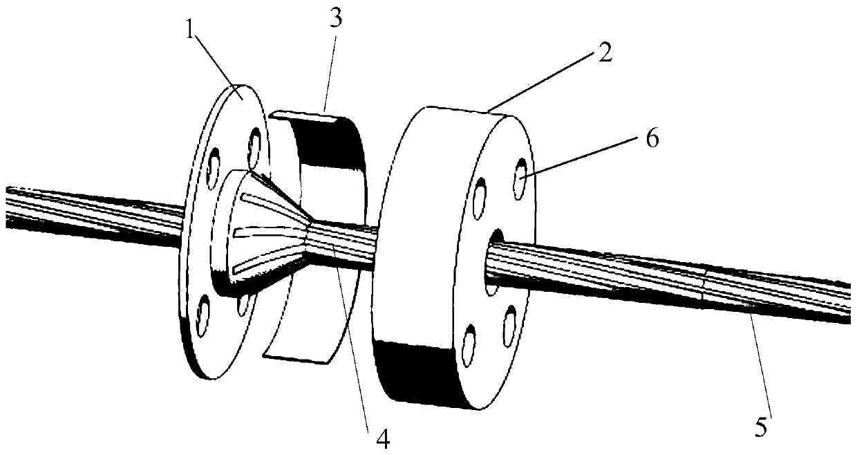
[0032] Such as figure 1 Shown is a high-temperature superconducting cable end connection structure provided by the present invention, which includes a first end connection structure 1 and a second end connection structure 2.

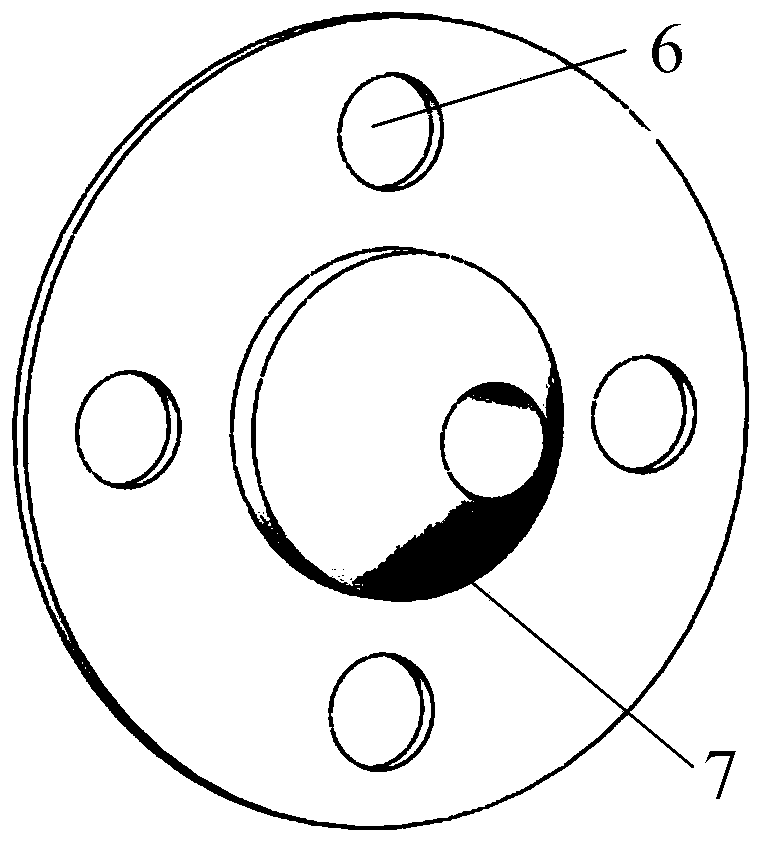
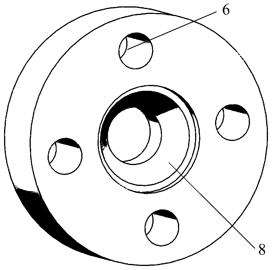
[0033] Such as figure 2 As shown, the middle of the first end connection structure 1 has a tapered slope structure 7 and a central through hole for the high temperature superconducting cable to pass through. Such as image 3 As shown, the second end connecting structure 2 has a tapered hole 8 to cooperate with the tapered ramp structure 7.

[0034] The first end connection structure 1 and the second end connection structure 2 are respectively provided with bolt holes 6 to be matched ...


PUM


Abstract

The invention relates to an end connection structure and method for a high-temperature superconducting cable. The structure comprises a first end connection structure and a second end connection structure. In a to-be-connected superconducting strip material layer, each superconducting strip material is connected with one transition copper strip material. The end connection structure passes throughthe high-temperature superconducting cable, and the transition copper strip materials are clamped and fixed through the end connection structure. Finally, a current lead wire is connected to the endconnection structure. The transition copper strip materials prevent the direct welding of a superconducting strip material with the current lead wire, and the contact parts of the transition copper strip materials with the end connection structure are not welded, thereby preventing the end welding process from affecting other superconducting material layers. Each superconducting strip material isindependently welded with the corresponding transition copper strip material, thereby facilitating the control of the welding length. The connection of the end connection structure and the current lead wire is bolt connection, thereby facilitating the assembly, disassembly and transportation. According to the invention, one lead wire can be independently led out of any conductor layer, and a current of each cable layer can be controlled independently.

Description

Technical field [0001] The invention belongs to the technical field of superconducting engineering, and particularly relates to a connection structure and a connection method of a high-temperature superconducting cable end. Background technique [0002] With the commercialization of high-temperature superconducting tapes, high-temperature superconducting power transmission developed using high-current-carrying density high-temperature superconducting tapes has been further developed. Compared with conventional transmission cables, high-temperature superconducting cables have become a promising direction in the development of future power technology due to their advantages of large capacity, low loss, small size, light weight and increased system flexibility. From the perspective of transmission loss, the high-temperature superconducting AC cable loss (including cooling loss) is 50% to 60% of the traditional cable, and the high-temperature superconducting DC cable can be reduced t...

Claims


Application Information

Patent Timeline
Patent Type & Authority Patents(China)
IPC IPC(8): H01R4/50H01R4/68H01R43/033
CPCH01R4/5016H01R4/68H01R43/033
Inventor 张瀚王银顺皮伟王蒙薛济萍
Owner NORTH CHINA ELECTRIC POWER UNIV (BAODING)
Learn More