
Iron-carbon micro-electrolysis process for introducing ozone and treating waste water

A technology of iron-carbon micro-electrolysis and wastewater treatment, which is applied in water/sewage treatment, water/sewage treatment equipment, water/sludge/sewage treatment, etc. It can solve the problems of increased electromotive force, color change, and high treatment cost, and achieve a reduction Comprehensive cost, lower pH value, and ensure the effect of no color return

Inactive Publication Date: 2018-05-15
江苏森博环保科技发展有限公司
View PDF5 Cites 4 Cited by
  • Summary
  • Abstract
  • Description
  • Claims
  • Application Information

AI Technical Summary

Problems solved by technology

This improved iron-carbon micro-electrolysis process is currently a commonly used method. Compared with the original iron-carbon micro-electrolysis process, this process improves the electromotive force of the primary battery, reduces the compaction of fillers, and improves the wastewater treatment effect. The improved iron-carbon micro-electrolysis process still has problems: the electromotive force still needs to be increased; there are many organic substances in the wastewater that cannot be treated; the wastewater is required to work at a lower pH value (1-3), and the acid used to adjust the pH value, The amount of alkali is large; the dissolved iron is more; a large amount of physical and chemical sludge is produced after neutralization and precipitation, and the treatment cost is high; the iron in the effluent is Fe 2+ Exist in form, form Fe(OH) after neutralization 2 Precipitation, it is difficult to precipitate completely when 6≤pH3 , the color reversion phenomenon occurs

Method used


Image

  • Iron-carbon micro-electrolysis process for introducing ozone and treating waste water

Examples


Embodiment 1

[0034] The waste water with COD=30000 mg / L is treated by adopting the iron-carbon micro-electrolysis process of the present invention.

[0035] S1, with the sulfuric acid solution of 4.5mol / L and the sodium hydroxide solution that the mass fraction is 15%, the pH of waste water is adjusted to 4;

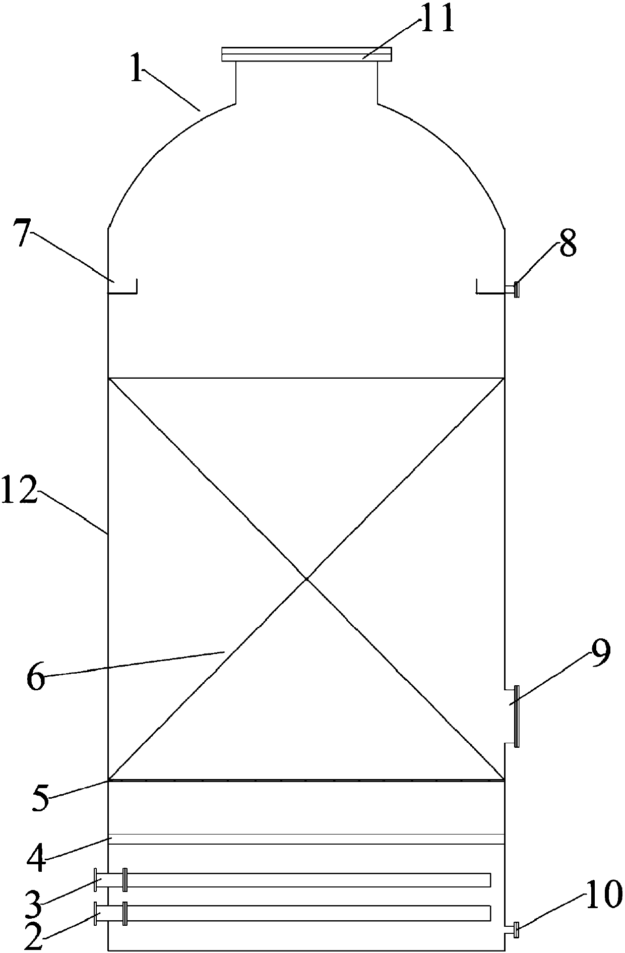
[0036] S2, after filtering the waste water with a pH of 4 in S1, transport it from the water inlet pipe 2 to the reaction tank 1, wherein the iron-carbon filler layer 6 is filled in the reaction chamber 12, and the mass ratio of iron filings and carbon particles in the iron-carbon filler layer 6 It is 1:2. After the waste water submerges the iron-carbon packing layer 6, the ozone is transported from the air inlet pipe 3 to the reaction tank 1. The ozone input amount per cubic meter of waste water is 10g. After 2 hours of reaction, the treated waste water is discharged from the overflow tank 7 and outlet pipe 8 discharge the iron-carbon micro-electrolysis reactor;

[0037] S3, transp...

Embodiment 2

[0040] The waste water with COD=18000mg / L is treated by adopting the iron-carbon micro-electrolysis process in the present invention.

[0041] S1, the pH of waste water is adjusted to 5 with the sulfuric acid solution of 9.2mol / L and the sodium hydroxide solution of 30% by mass fraction;

[0042] S2, after filtering the waste water with a pH of 5 in S1, transport it from the water inlet pipe 2 to the reaction tank 1, wherein the iron-carbon filler layer 6 is filled in the reaction chamber 12, and the mass ratio of iron filings and carbon particles in the iron-carbon filler layer 6 1:3, after the waste water submerges the iron-carbon filler layer 6, the ozone is transported from the air inlet pipe 3 to the reaction tank 1, and the input amount of ozone per cubic meter of waste water is 8g. The water tank 7 and the water outlet pipe 8 discharge the iron-carbon micro-electrolysis reactor;

[0043] S3, transporting the wastewater output from the iron-carbon micro-electrolysis react...

Embodiment 3

[0046] The waste water with COD=13000mg / L is treated by adopting the iron-carbon micro-electrolysis process in the present invention.

[0047] S1, the pH of waste water is adjusted to 2 with the sulfuric acid solution of 6.5mol / L and the sodium hydroxide solution of 20% by mass fraction;

[0048] S2, after filtering the waste water with a pH of 2 in S1, transport it from the water inlet pipe 2 to the reaction tank 1, wherein the iron-carbon filler layer 6 is filled in the reaction chamber 12, and the mass ratio of iron filings and carbon particles in the iron-carbon filler layer 6 It is 1:2.5, after the waste water submerges the iron-carbon filler layer 6, the ozone is transported from the air inlet pipe 3 to the reaction tank 1, and the input amount of ozone per cubic meter of waste water is 9g. 7 and outlet pipe 8 discharge the iron-carbon micro-electrolysis reactor;

[0049] S3, transporting the wastewater output from the iron-carbon micro-electrolysis reactor in S2 to the...


PUM


Abstract

The invention discloses an iron-carbon micro-electrolysis process for introducing ozone and treating waste water. The iron-carbon micro-electrolysis process comprises the following steps: S1, adjusting the pH of the waste water to 2 to 9 by utilizing an acid solution / alkali solution; S2, filtering the waste water with the pH of 2 to 9 in S1, outputting the waste water into an iron-carbon micro-electrolysis reactor, introducing ozone into the iron-carbon micro-electrolysis reactor, reacting for 1h to 3h, and discharging the waste water out of the iron-carbon micro-electrolysis reactor; and S3,transporting the waste water outputted from the iron-carbon micro-electrolysis reactor into a neutralizing precipitating pond to be precipitated. Compared with the prior art, the iron-carbon micro-electrolysis process has the beneficial effects that the treatment capacity for organic matters in the waste water can be improved, the color reversion phenomenon can be well overcome, the pH range of the waste water entering the iron-carbon micro-electrolysis reactor can be enlarged, the consumption of acid and alkali can be reduced, the generation amount of the neutralized precipitated sludge is reduced, and the comprehensive treatment cost of the waste water can be reduced.

Description

technical field [0001] The invention belongs to the technical field of waste water treatment, and in particular relates to an iron-carbon micro-electrolysis process for passing through ozone for waste water treatment. Background technique [0002] The iron-carbon micro-electrolysis method, also known as the internal electrolysis method, iron-carbon method, iron filings filtration method, zero-valent iron method, etc., is widely used in the treatment of high-concentration organic wastewater such as pesticides, medicines, and dyes. The research on iron-carbon micro-electrolysis began in the 1960s. This method mainly uses micro-batteries composed of metal corrosion principles to treat wastewater. In the 1970s, scientists from the former Soviet Union used iron filings for printing and dyeing wastewater treatment, and they were introduced into my country in the 1980s. The original iron-carbon micro-electrolysis process is a method of using iron filings and carbon particles to fo...

Claims


Application Information

Patent Timeline
IPC IPC(8): C02F1/461
CPCC02F1/46176C02F2201/4619C02F2201/784
Inventor 董庆华熊坤
Owner 江苏森博环保科技发展有限公司
Learn More