
Valve high-temperature high-pressure environment vertical arrangement test system

A high-temperature, high-pressure, test system technology, applied in the direction of measuring devices, mechanical parts testing, fluid tightness testing, etc., can solve problems such as easy wear of valve seals, leakage of test working fluid, inconsistent vertical layout, etc. The effect of high uniformity

Active Publication Date: 2018-05-11
CHINA UNITED ENG
View PDF5 Cites 0 Cited by
  • Summary
  • Abstract
  • Description
  • Claims
  • Application Information

AI Technical Summary

Problems solved by technology

[0005] The applicant has Chinese patents with application numbers 201621184464.3 and 201610961033.1, which have realized the life test and air tightness test of high-temperature and high-pressure gas for valves. However, the high-temperature furnace design used in this patent technology has valves that are arranged in a horizontal position, that is, the motor actuator is arranged in a horizontal position. , which is inconsistent with the vertical arrangement of the valve in actual use; and the valve seal is easy to wear due to uneven force, resulting in leakage of the test working fluid

Method used


Image

  • Valve high-temperature high-pressure environment vertical arrangement test system
  • Valve high-temperature high-pressure environment vertical arrangement test system
  • Valve high-temperature high-pressure environment vertical arrangement test system

Examples


Embodiment Construction

[0025] The present invention will be further described in detail below in conjunction with the accompanying drawings and examples. The following examples are explanations of the present invention and the present invention is not limited to the following examples.

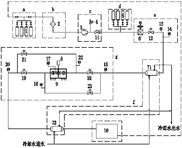
[0026] see Figure 1 to Figure 5 , the embodiment of the present invention includes a gas source system a, a filter system b, a pressurization system c, a pressure stabilization system d, a pressure regulation system e, a cooling system f, a main measurement control system g and a helium recovery device 10.

[0027] The gas source system a is provided with a helium cylinder group 1 as the gas source of the system. The use of helium has higher safety.

[0028] The filter system b is provided with a filter 2 .

[0029] The booster system c is provided with a booster pump 3 , a safety valve 4 , and a check valve 11 . The booster pump 3 is used to pressurize the helium in the low-pressure helium cylinder set 1, so as...


PUM


Abstract

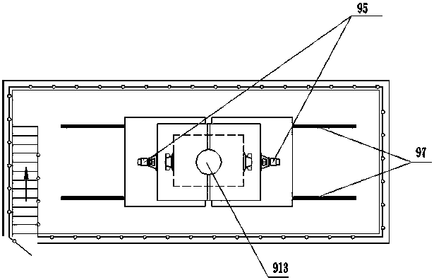
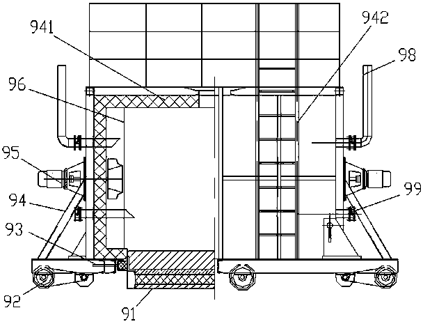
The invention provides a valve high-temperature high-pressure environment vertical arrangement test system, which can meet vertical installation test of a valve. The system comprises a gas source system, a filter system, a pressure booster system, a pressure stabilizing system, a pressure regulating system, a cooling system and a master measurement control system. A furnace platform is fixedly arranged on the ground of a ground pit; rails are paved on the ground of the ground pit; a furnace body is mounted on the rails through walking devices, and covers the furnace platform; and the inner space of the furnace body forms a test room. The furnace body is divided into a left furnace body and a right furnace body, which can move at the two sides of the furnace platform to realize open and close. The top portion of the furnace body is provided with a preformed hole. A motor actuating mechanism is vertically arranged, and is used for connecting and controlling a valve rod vertically extending out of the preformed hole. The left furnace body and the right furnace body are respectively provided with a circulating fan, a flow guiding device, an exhaust device and an air inlet device, wherein the circulating fans, the exhaust devices and the air inlet devices are communicated with the inner space of the furnace body. An electric heater device is mounted on the furnace body.

Description

technical field [0001] The invention relates to a vertical test system for a valve in a high temperature and high pressure environment. Background technique [0002] The valve life test refers to the cycle test of the valve under specific test conditions to investigate the change of various failure modes over time such as its life characteristics and failure rules, and to test for the rationality of valve structure design, sealing performance, processing quality, and material selection. Provide basic data for reliability design, prediction, and improvement of new product quality. [0003] The valve air tightness test mainly checks the internal leakage and external leakage of the valve. The internal leakage of the valve refers to the gap between the valve core and the valve body due to the erosion and wear of the medium, which is not tightly closed, and the medium can flow through. Leakage of the valve means that the seal between the valve and the connecting flange or conne...

Claims


Application Information

Patent Timeline
Patent Type & Authority Applications(China)
IPC IPC(8): G01M13/00G01M3/28
CPCG01M3/2876G01M13/00Y02E30/30
Inventor 曾鹏张伟光朱建明
Owner CHINA UNITED ENG
Learn More