
Using method of rotary type microwave metallurgical furnace

A microwave metallurgy and rotary technology, applied in the direction of rotary drum furnace, furnace, furnace type, etc., can solve the problems of reducing heating efficiency, material spillage, heat loss, etc., to improve heating efficiency, uniform and sufficient heating, and prevent heat loss churn effect

Inactive Publication Date: 2018-05-08
陕西盛华冶化有限公司
View PDF4 Cites 9 Cited by
  • Summary
  • Abstract
  • Description
  • Claims
  • Application Information

AI Technical Summary

Problems solved by technology

[0003] However, the existing microwave metallurgical furnaces are generally fixed and heated directly by microwaves, so that the material in the outer layer is heated faster than the material in the inner layer, so that the heating is not uniform and sufficient, and the heating efficiency is reduced. Some microwave metallurgical furnaces, It cannot be insulated and heat-preserved, which will easily cause heat loss, increase the heating time, and waste energy. There are also microwave metallurgical furnaces, which are troublesome to enter and exit materials, and easily cause materials to spill out, resulting in waste. The operation is cumbersome and inconvenient to use. It is far from meeting the current people's requirements for this product

Method used


Image

  • Using method of rotary type microwave metallurgical furnace
  • Using method of rotary type microwave metallurgical furnace

Examples


Embodiment Construction

[0017] The present invention will be further described below in conjunction with specific embodiments, wherein, the accompanying drawings are only for exemplary illustrations, and what is shown is only a schematic diagram, rather than a physical map, and cannot be understood as a limitation to this patent. In order to better illustrate the present invention Specific embodiments, some parts in the drawings will be omitted, enlarged or reduced, and do not represent the size of the actual product. For those skilled in the art, it is understandable that some known structures and their descriptions in the drawings may be omitted. Based on The specific implementation modes in the present invention and all other specific implementation modes obtained by persons of ordinary skill in the art without making creative efforts all belong to the protection scope of the present invention.

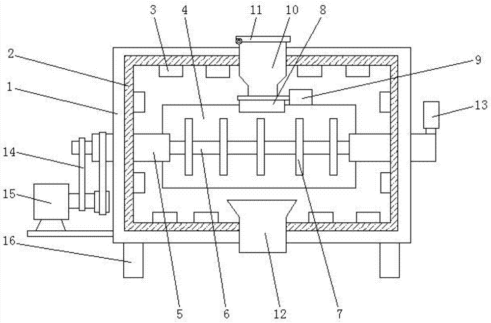
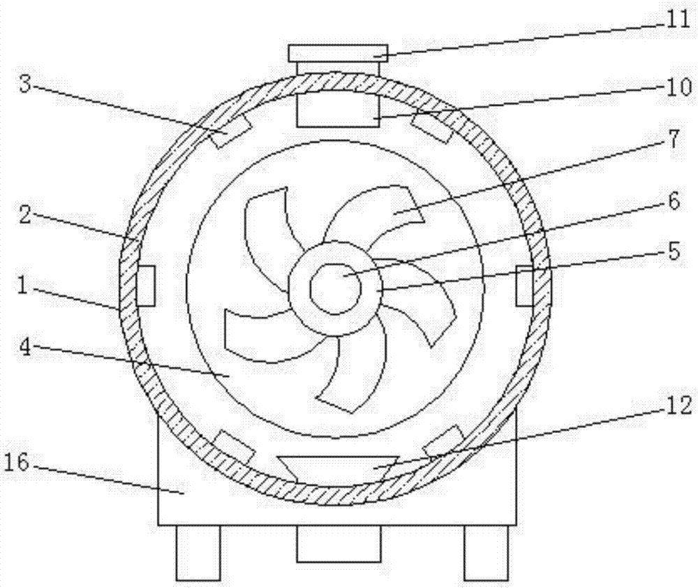
[0018] see Figure 1-Figure 2 , the present invention provides a technical solution: a method for usin...


PUM


Abstract

The invention discloses a using method of a rotary type microwave metallurgical furnace. An inner separating layer is attached to the inner wall of a furnace body, a plurality of magnetrons are installed on the inner wall of the inner separating layer and are evenly and symmetrically distributed, a horizontal furnace pipe is arranged in the center of an inner cavity of the furnace body, the left and right ends of the furnace pipe are rotationally connected to the left and right sides of the furnace body through an external rotating shaft correspondingly, the left end of the external rotating shaft penetrates the left side of the furnace body, an internal rotating shaft transversely penetrating the furnace body and the furnace pipe can be rotationally connected to the interior of the external rotating shaft, a plurality of rotating blades are welded to the internal rotating shaft and are evenly distributed to an inner cavity of the furnace pipe, a feeding opening is formed in the top ofthe furnace pipe, and a pneumatic gate valve is arranged at the top of the feeding opening. The rotary type microwave metallurgical furnace is simple in structure, stable, reliable, safe, efficient,even in microwave transmission and capable of achieving heat isolation and heat preservation; through dual rotation of the furnace pipe, material heating is more even and sufficient, and the smeltingefficiency is improved.

Description

technical field [0001] The invention relates to the technical field of metallurgical equipment, in particular to a method for using a rotary microwave metallurgical furnace. Background technique [0002] Microwave metallurgy is a new metallurgical technology that applies microwave energy to metallurgical units and uses its characteristics of selective heating, internal heating and non-contact heating to strengthen the reaction process. The advantage is that it can realize rapid and selective heating of powdery materials, and avoid the phenomenon of uneven heat and mass transfer of powdery materials caused by traditional heating methods. Experiments show that microwave heating can be used without using binders. Poor manganese ore powder and coal powder are fully mixed, and sent to a microwave heating device for bulk reduction under powder conditions to obtain pure low-carbon sponge ferromanganese, which is of great significance for improving the metallurgical reaction rate. ...

Claims


Application Information

Patent Timeline
Patent Type & Authority Applications(China)
IPC IPC(8): F27B7/02F27B7/10F27B7/18F27B7/22F27B7/26F27B7/34
CPCF27B7/02F27B7/10F27B7/18F27B7/22F27B7/26F27B7/34
Inventor 庞建明马永宁
Owner 陕西盛华冶化有限公司
Learn More